
Methods and apparatus for controlling heart assist devices

Inactive Publication Date: 2007-01-30
ARROW INT INC
View PDF21 Cites 95 Cited by
  • Summary
  • Abstract
  • Description
  • Claims
  • Application Information

AI Technical Summary

Benefits of technology

[0013]A suitable embodiment is a real time computing programme based on a Windkessel model which comprises three elements, namely a characteristic input resistance, Rao, an arterial compliance, Cw, and a peripheral resistance, Rp. Rao is the resistance that is experienced by the heart, Cw is the compliance which represents the ability of the arterial vascular bed to store a specific volume of blood by means of elastic expansion, and Rp is the peripheral resistance beyond which the stored volume of blood runs off. An advantage of the three-element Windkessel model is that the shape of the computed blood flow rate depends to a minor degree on the values that are used for the elements. As a result, the closing time of the aortic valve can be predicted with great accuracy and thereby the heart assist device can be controlled in an effective manner.

Problems solved by technology

In the case of too late inflation of the IAB, its operation will be less effective.
A disadvantage of this system is that the times that have been set will deviate from the desired times with every acceleration or deceleration of the cardiac cycle, so that said times constantly need to be reset.
Furthermore it is impossible to take into account the possibility of an irregular cardiac cycle, which often occurs with those people for whom the IABP is intended.
Thereby, in particular the setting of the inflation time of the IAB is carried out incorrectly in many cases.
However, the time at which the IAB is to be inflated cannot be determined by means of said apparatus.
Said apparatus is not accurate enough in those cases where the heartbeat is irregular.
Said device is not accurate enough in the case of a damped blood pressure signal or in the case of irregular heartbeats.
However, even a correct determination of the closing time of the aortic valve (incisura point) results in a too late inflation of the intra-aortic balloon due to the mechanical properties of an IABP system.

Method used


Image

  • Methods and apparatus for controlling heart assist devices
  • Methods and apparatus for controlling heart assist devices
  • Methods and apparatus for controlling heart assist devices

Examples


Embodiment Construction

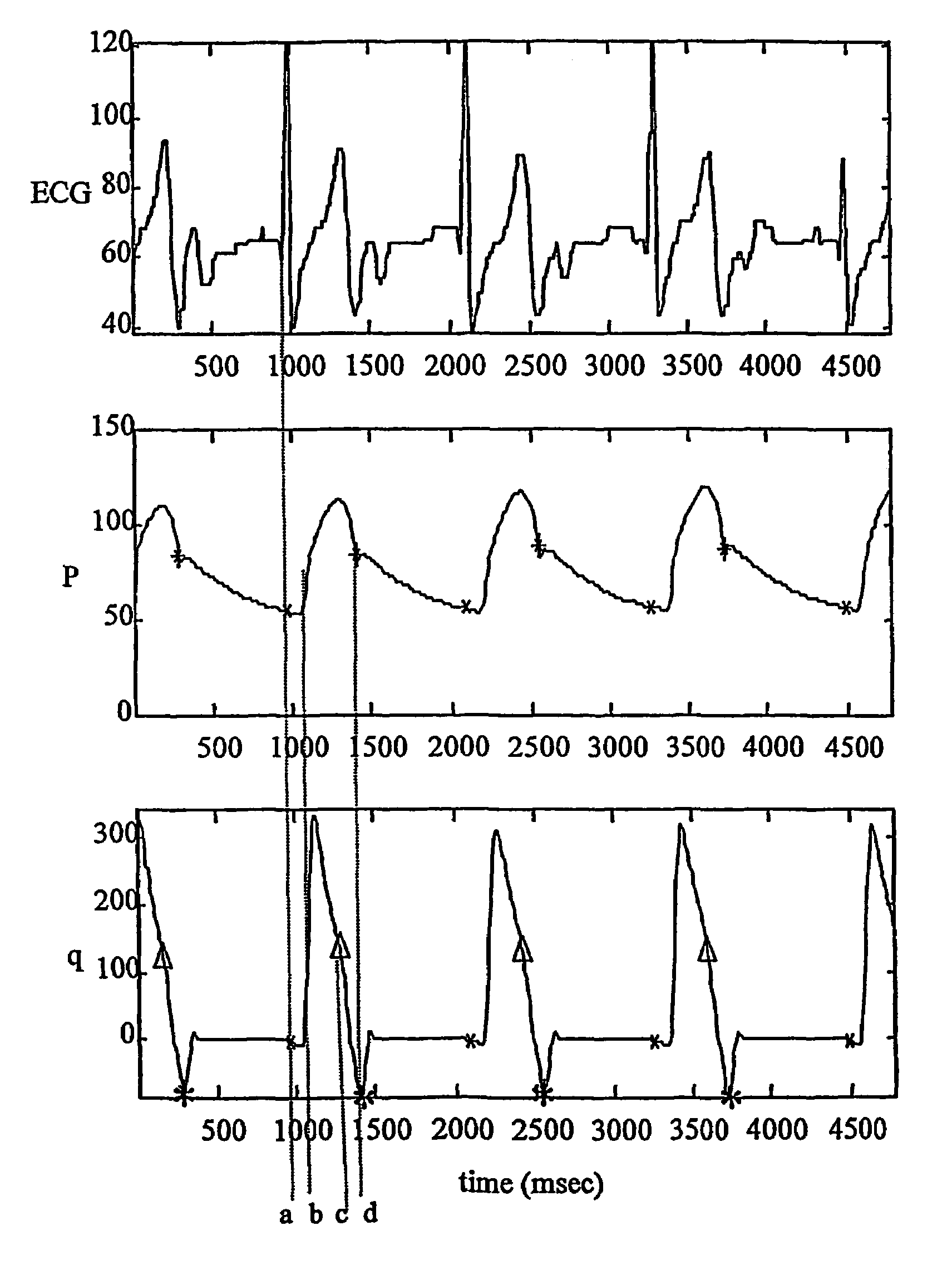
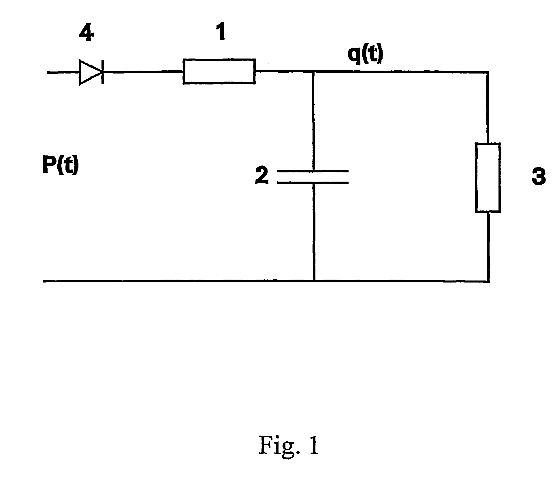
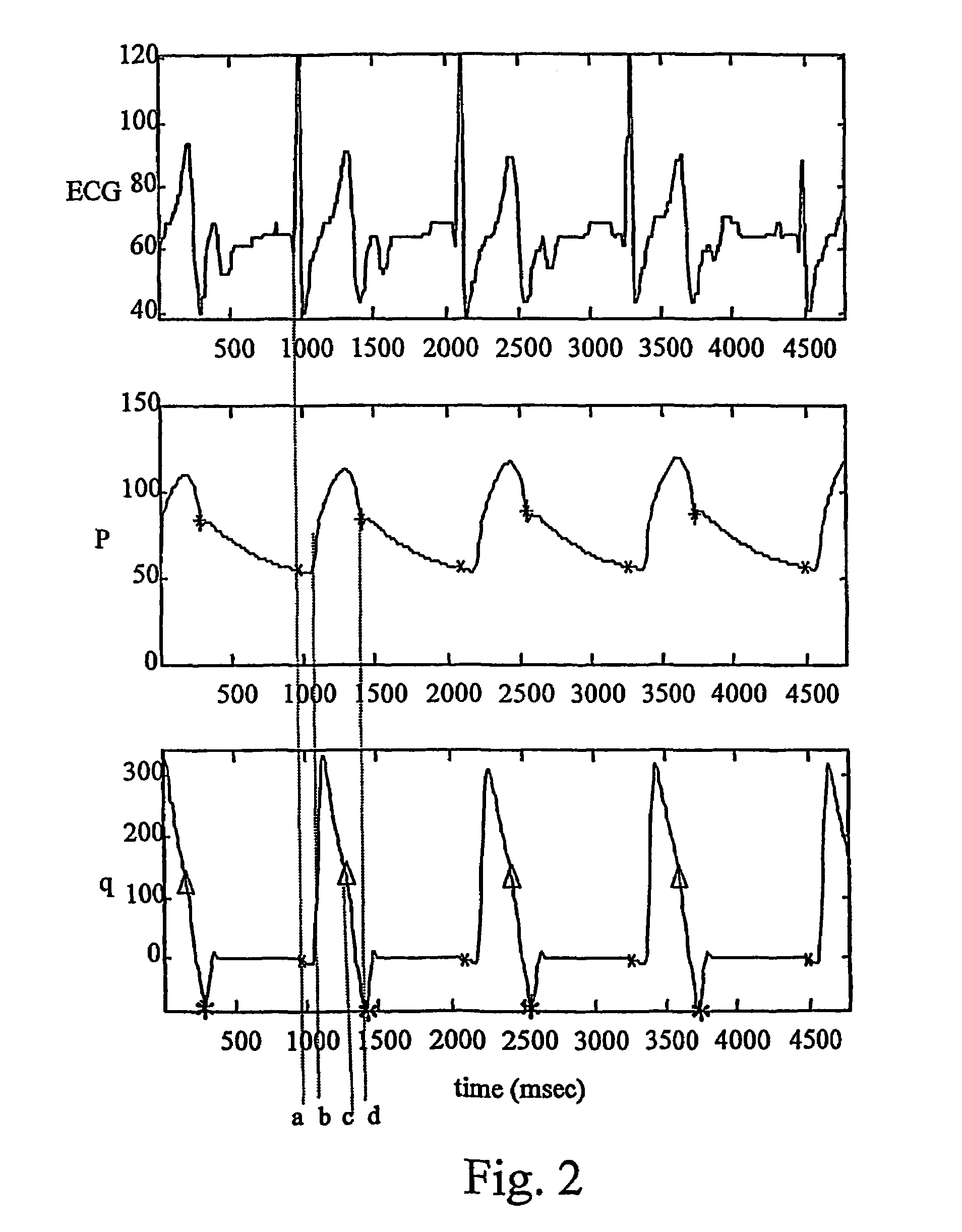
[0020]Before describing the invention in detail, it is useful to describe the principles of the invention first with reference to FIGS. 1, 2, 3.

[0021]FIG. 1 shows a Windkessel model which is an equivalent circuit diagram of the heart valve and the arterial vascular system describing the load on the heart. The model comprises the following elements: a characteristic input resistance, Rao, 1; an arterial compliance, Cw, 2; a peripheral resistance, Rp, 3; and a heart valve, D, 4, which closes after the blood flow rate in the cardiac cycle becomes negative. On the basis of this model, a mathematical equation can be written, which gives the relation between the arterial pressure signal, P(t) and the blood flow rate, q(t):

(1+Rao / Rp).q(t)+Rao.Cw.q′(t)=P(t) / Rp+Cw.P′(t)

wherein q′ (t) and P′ (t) are the first-order derivatives in time of q(t) and P(t).

[0022]The value q(t) that is computed by means of this equation is undelayed in time. The closing time of the heart valve can be accurately de...


PUM


Abstract

An apparatus for a heart assist device, comprising a processing unit for computing the blood flow rate from the arterial pressure curve and for predicting at every heartbeat the closing time of the heart valve from the curve of the blood flow rate. The processing unit is adapted to deliver a signal for controlling a heart assist device at a point in time, a period ahead in time of the closing time of the heart valve, wherein the mechanical properties of the said heart assist device are taken into account in determining the period. The apparatus adapts itself to changes in a patient's heart frequency and aortic pressure.

Description

CROSS-REFERENCE TO RELATED APPLICATIONS[0001]This application is a 35 U.S.C. §371 national stage filing of PCT International Application No. PCT / NL01 / 00713, filed Oct. 1, 2001, which claims priority of Dutch Patent Application No. 1016320, filed Oct. 3, 2000, the contents of both of which are hereby incorporated by reference.FIELD OF THE INVENTION[0002]The invention relates to methods and apparatus for controlling a heart assist device, for example intra-aortic balloon pumps and auxiliary artificial hearts.BACKGROUND OF THE INVENTION[0003]An intra-aortic balloon pump (IABP) comprises an intra-aortic balloon (IAB) and a pump device, wherein the IAB can be introduced for example into the aorta of a patient whose heart does not function properly.[0004]With every cardiac cycle, the IAB is inflated by means of a pump device at the end of an ejection phase of the left ventricle of the heart and deflated again before the next ejection phase begins. In this way, the pump action of the heart...

Claims


Application Information

Patent Timeline
IPC IPC(8): A61B5/02A61M1/10A61N1/362A61B5/0215A61M1/12A61B5/026A61B5/352A61M1/36
CPCA61B5/026A61B5/0456A61M1/1086A61B5/0215A61M1/3663A61M1/1072A61M1/1037A61M2205/3334A61M2205/33A61M2205/3303A61B5/352A61M60/546A61M60/139A61M60/196A61M60/515A61M60/295
Inventor JANSEN, JOZEF REINIER CORNELISSCHREUDER, JOHANNES JACOBUS
Owner ARROW INT INC
Learn More