Method and apparatus for repair of reflective photomasks

a technology of reflective photomasks and repair methods, applied in the field of laser light removal apparatus and methods for removing materials, can solve the problems of reflected wavefronts from each interfaces that are constructively interfering producing constructive interference in the backward or reflected direction, and defects that are therefore frequently encountered

Inactive Publication Date: 2007-01-30
GLOBALFOUNDRIES INC
View PDF17 Cites 34 Cited by
  • Summary
  • Abstract
  • Description
  • Claims
  • Application Information

AI Technical Summary

Benefits of technology

[0011]In this disclosure, we describe a method and apparatus that solves conventional problems which, in various aspects of embodiments of the invention, direct a relatively short pulse of light tuned to the wavelength of highest reflectivity of the substrate, and which ablates the absorbing defect in a non-thermal process which removes the defect without damaging the underlying reflective substrate.
[0012]In one aspect of the invention, defects in the patterned absorber atop a reflective substrate can be removed by directing an intense ultrashort duration laser pulse just above the defect in order to ablatively remove it, without damaging the underlying reflective mask. Another aspect of the invention provides a general method of performing an ablative process that leads to the specific removal of material. Another aspect of this invention provides a method of removing specific material imbedded in a matrix of different materials, without any repair induced damage or substrate pitting. In various aspects of embodiments of the invention, a mask may be repaired without degradation of reflectance in the defect region or in the region adjacent thereto.
[0015]In another embodiment of the invention, a method of repairing a defect on a mask includes providing a reflective substrate comprising the mask which includes a first region and a second region, wherein a light absorbing first material covers the first region and the second region is free of the light absorbing material; inspecting the mask and detecting an essentially opaque defect on the mask in a defect region; shining a plurality of laser pulses on the defect region to ablate the defect after selecting a laser pulse duration; and removing the defect without damaging the reflective substrate underlying the defect. In this aspect, the absorbing region may have an edge with an edge placement tolerance, wherein removing the defect leaves the edge of the absorbing region within the edge placement tolerance. The placement tolerance may be 10% or less, and the defect may be removed without splattering any defect material on the substrate, or without pitting the substrate.

Problems solved by technology

The layered materials have alternating relatively high and low dielectric constants such that the reflected wavefronts from each interface constructively interfere in the backward or reflected direction.
A phase shift of 180 degrees on reflection from each film produces constructive interference in the backward or reflecting direction.
The above-described conventional photomask manufacturing process usually results in at least some imperfections, and defects are therefore frequently encountered during inspection of the photomasks.
In advanced mask production, the defect rate per mask approaches 100%, which is unacceptable for cost-effective manufacturing.
When a defect is a bridge defect connected to an adjacent absorber line, as in FIG. 1, conventional laser ablation may damage that adjacent line, undesirably removing some wanted absorber from the line.
In addition, because a relatively high amount of thermal energy can be transmitted with the laser beam, the laser ablation step not only melts and vaporizes the unwanted metal defect region, it may also damage and remove a layer of substrate underlying and adjacent the opaque defect, producing roughness in the substrate.
However there are a number of problems that limit the use of FIB for mask repair.
Second, while an opaque defect is being removed, substrate at the edge of the defect is attacked at the same rate, and the result is a “river bed” or trench of damaged substrate around the defect.
Third, the focused ion beam species is typically gallium, and gallium has been found implanted into the substrate when the opaque defect is removed, causing reflectance losses.
Fourth, the sputtering of material by the ion beam leads to ejection of material in all directions, and some of this ejected material may come to rest on adjacent edges.
A more general problem involves the ablation of a specific material, patterned or otherwise, that resides in a matrix of other materials, without damaging the desirable materials surrounding the specific material to be removed.

Method used


Image

  • Method and apparatus for repair of reflective photomasks
  • Method and apparatus for repair of reflective photomasks
  • Method and apparatus for repair of reflective photomasks

Examples


Embodiment Construction

[0028]It should be noted with the disclosure herein that the use of prepositions, such as “on”, “over”, and “under”, are defined with respect to a planar surface of the mask, regardless of the orientation in which the mask is actually held. A layer may be considered to be “on” another layer even if there are intervening layers.

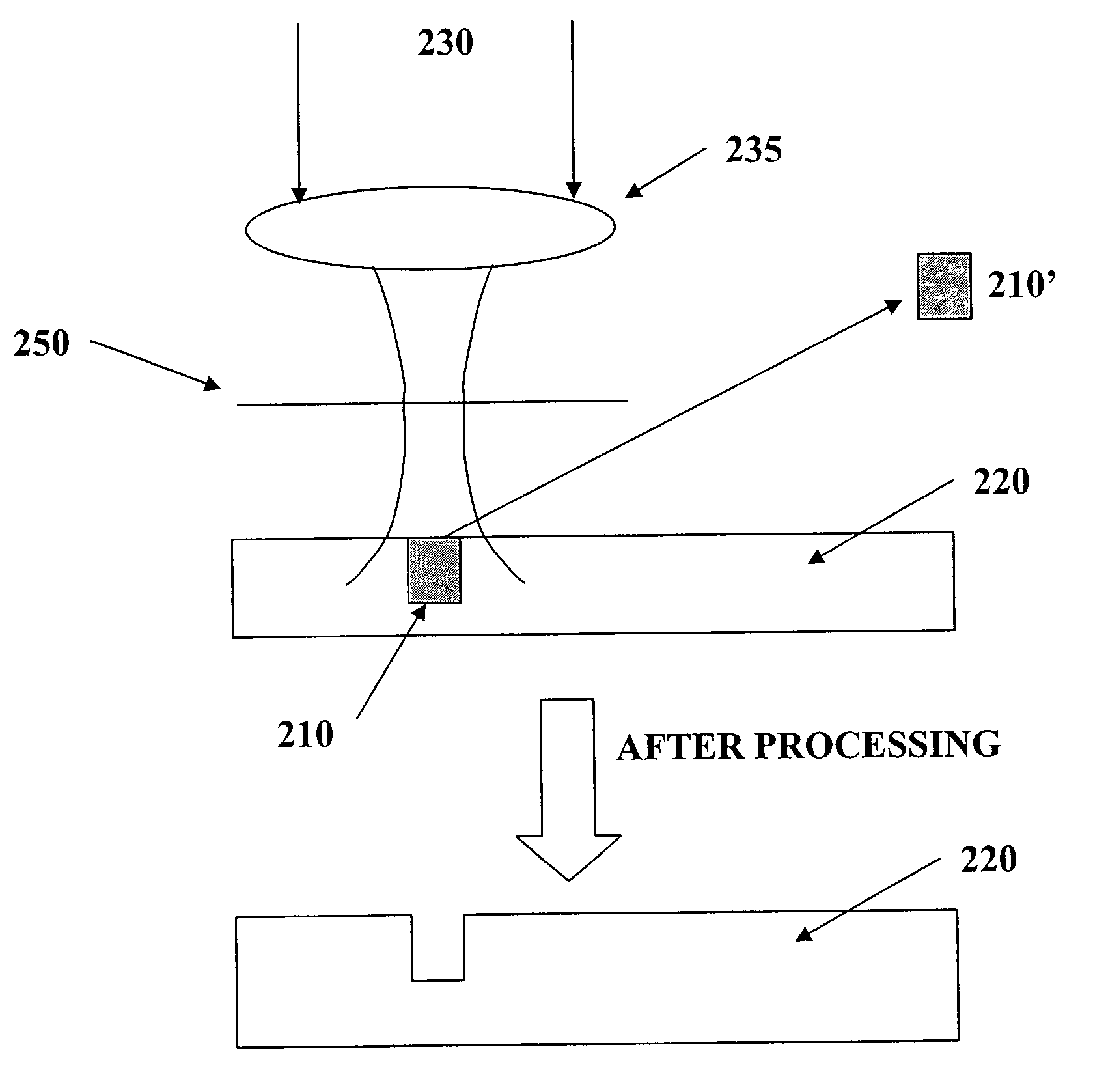
[0029]The method of one embodiment of the invention ablatively removes specific material using ultrashort pulses of laser light. By tuning the laser output wavelength to match or be set within a specific offset of a wavelength specific absorption of the material that is desired to be removed, discrimination between this particular material and adjacent desirable materials, all or part of which may be embedded in a matrix, can be achieved.

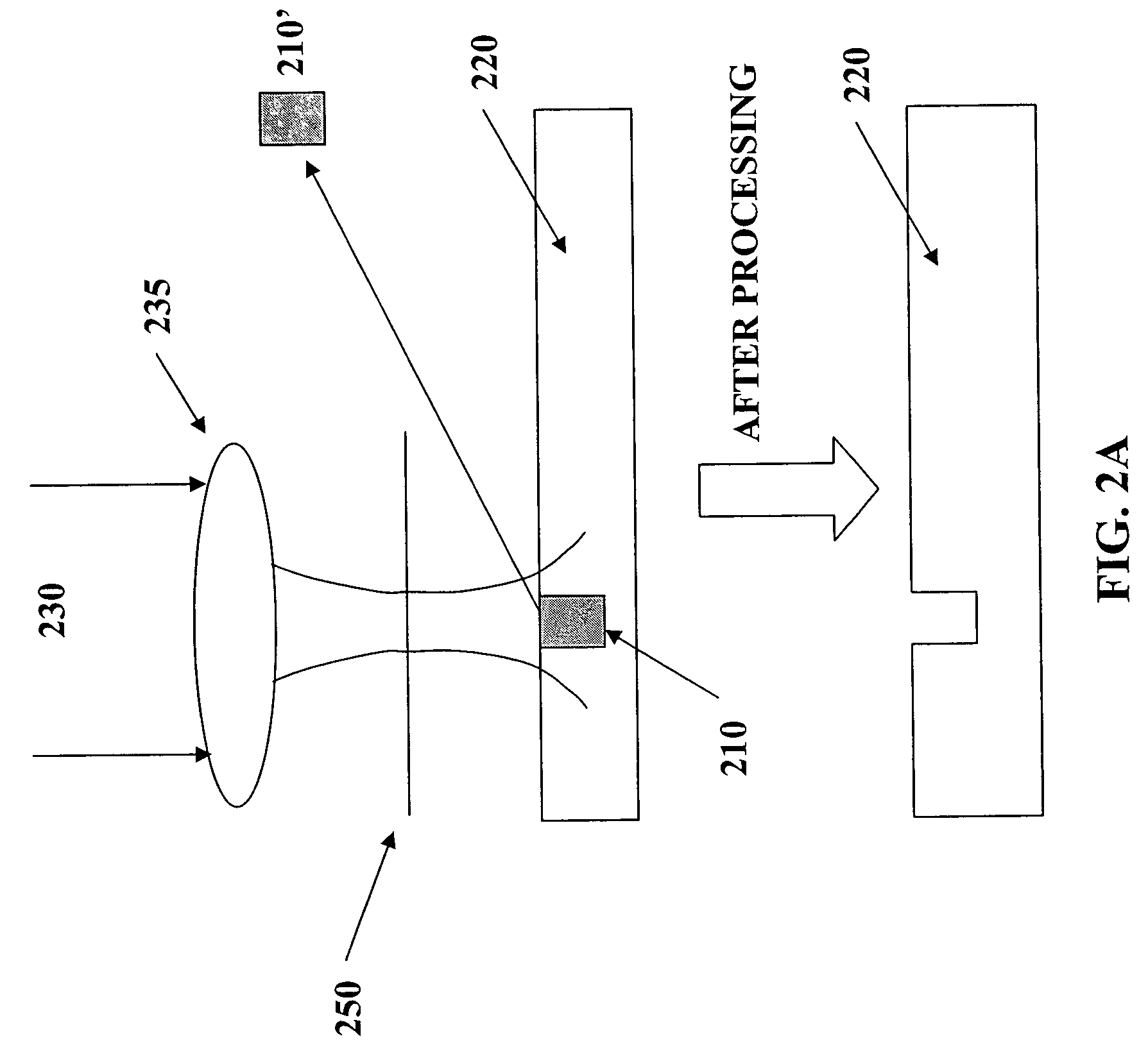
[0030]For example, and with reference to FIGS. 2A and 2B, if a first material 210 possesses an atomic core level at energy E1, and if a second material 220 possesses an atomic core level at E2, by tuning the wavelength of ultr...


PUM

PropertyMeasurementUnit
reflectivityaaaaaaaaaa

Abstract

A method of selectively ablating an undesired material from a substrate includes providing a substrate with two regions; providing laser pulses; tuning a wavelength of the laser pulses to match a desired wavelength characteristic of a material and directing the tuned laser pulses onto the substrate; and controlling a pulse duration, wavelength, or both, of the laser pulses to ablate the undesired material without damaging the substrate or any adjacent material. In another embodiment, an apparatus for repairing a defect on a reflective photomask includes a femtosecond pulse width laser; a harmonic conversion cell; a filter for passing a selected EUV harmonic of the laser light; a lens arrangement configured to direct the selected EUV harmonic of the laser light onto the photomask; and a control unit connected to the laser to control an ablation of the defect on the reflective photomask.

Description

BACKGROUND OF THE INVENTION[0001]This invention generally relates to an apparatus and method for removal of materials using laser light. More particularly, it relates to matching the wavelength of an ultrashort laser pulse to the absorption characteristics of the material being removed, in order to enhance the removal or ablation of one material, while leaving adjacent materials with different absorption properties undisturbed. Even more particularly, it relates to the use of ultrashort duration laser pulses to repair opaque defects on reflective photomasks. More particularly it relates to the removal of defects on reflective photomasks by matching the wavelengths of the ablative laser light to the peak of the reflectance of the underlying photomask substrate.[0002]Photomasks are extensively used in the fabrication of integrated circuits on semiconductor wafers. While standard photomasks include a patterned absorbing or opaque film on a transparent substrate, a reflective mask inclu...

Claims


Application Information

Patent Timeline
Patent Type & Authority Patents(United States)
IPC IPC(8): B23K26/38B23K26/06B23K26/40G03F1/00
CPCB23K26/0635B23K26/365B23K26/4015B23K26/407G03F1/72B82Y10/00B82Y40/00G03F1/24B23K26/4095B23K26/0624B23K26/40B23K26/361B23K2101/35B23K2103/50
Inventor HAIGHT, RICHARD A.LONGO, PETER P.WAGNER, ALFRED
Owner GLOBALFOUNDRIES INC
Why Eureka
Try Eureka