Apparatus and method for constant delta current control in a capacitor charger

a capacitor charger and constant delta current technology, applied in the direction of electric variable regulation, process and machine control, instruments, etc., can solve the problems of high switching loss, inefficient operation, and inability to set the charging current i/sub>p/sub> of the charger b>200/b>, so as to prevent the transformer from magnetic saturation and no power loss, simple and precise control

Inactive Publication Date: 2007-01-30
RICHTEK TECH
View PDF7 Cites 10 Cited by
  • Summary
  • Abstract
  • Description
  • Claims
  • Application Information

AI Technical Summary

Benefits of technology

[0006]Another object of the present invention is to provide an apparatus and method for a capacitor charger without introducing power loss resulted from current detection.
[0009]From one aspect of the present invention, it is easy to determine and set the delta current flowing through the primary or secondary winding of the transformer, thereby achieving simple and precise control.
[0010]From another aspect of the present invention, the delta current of the primary winding of the transformer is independent of the input voltage connected to the primary winding, thereby preventing the transformer from magnetic saturation.
[0011]From still another aspect of the present invention, there are no current sense resistors connected in series to the current path of the primary or secondary winding of the transformer, thereby introducing no power loss resulted therefrom.
[0012]According to the present invention, the on-time period of the switch varies with the input voltage, and therefore the influence to the delta current of the primary current resulted from the variation of the input voltage is eliminated, resulting in the delta current of the charging current could be a constant value and easily to set. In addition, the secondary current could be precisely controlled due to the off-time control, and therefore, the maximum of the primary current and the minimum of the secondary current both could be controlled in a desired range, thereby no magnetic saturation occurred to the transformer. Moreover, no current sense to the primary winding of the transformer is used to determine the on-time period of the switch, and thus there will be no power loss resulted from current detection to be introduced.

Problems solved by technology

Although the capacitor charger 100 is cheaper, the transformer T1 has a more complicated structure to construct the circuit, and the power transistor Q1 causes higher switching loss.
In addition, there are too many parameters effective to the current IP, for example the input voltage Vin, transformer T1 and power transistor Q1, for the current IP to be precisely controlled.
Furthermore, the charging current IP of the charger 200 is not easy to set.
In the capacitor charger 300, it is the maximum duty of the transistor 308 to be used to determine the charging current IP, and unfortunately, which is easy to have the transformer T1 to be magnetically saturated and inefficiently operated.
Moreover, the input voltage Vbat is supplied by battery, and it will decade as time goes by, resulting in longer and longer charging time for the capacitor C1 to reach the same voltage.

Method used


Image

  • Apparatus and method for constant delta current control in a capacitor charger
  • Apparatus and method for constant delta current control in a capacitor charger
  • Apparatus and method for constant delta current control in a capacitor charger

Examples


Embodiment Construction

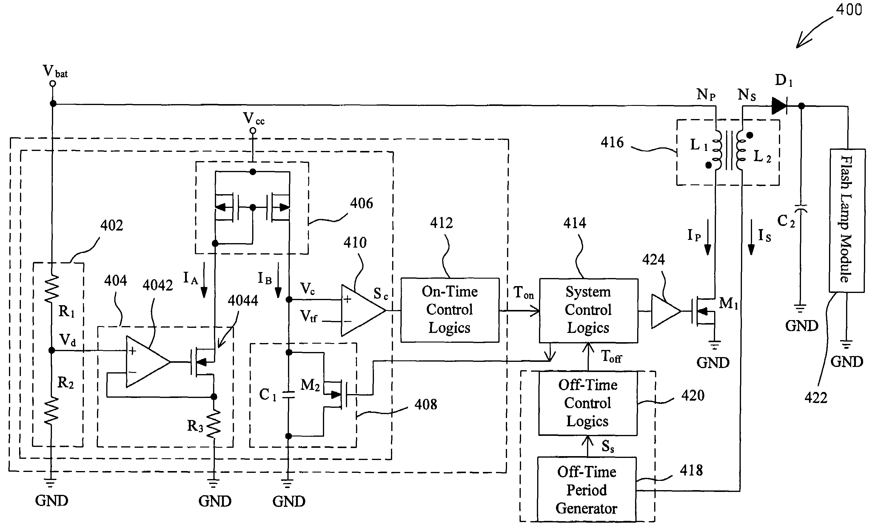
[0019]FIG. 4 shows an application of one embodiment according to the present invention for a flash lamp module. In a capacitor charger 400, a transformer 416 has a primary winding L1 and a secondary winding L2 with a turns ratio NP:NS, a transistor M1 is connected between the primary winding L1 and ground GND, and the primary current IP flowing through the primary winding L1 is controlled by the switching transistor M1. Briefly, the capacitor charger 400 has system control logics 414 to switch the transistor M1 through a driver 424 in response to an on-time decision circuit and an off-time decision circuit. The on-time decision circuit includes on-time control logics 412 to determine the on-time period Ton for the transistor M1 according to the output SC generated by an on-time period generator that includes a voltage generator 402, a current source 404, a current mirror 406, a charge / discharge circuit 408, and a comparator 410. On the other hand, the off-time decision circuit inclu...


PUM


Abstract

In a capacitor charger, a transformer has a primary winding connected between an input voltage and a switch for generating a primary current flowing through the primary winding by switching the switch to thereby induce a secondary current flowing through a secondary winding of the transformer and a secondary voltage tapered from the secondary winding, a control apparatus and method adjusts the on-time period for the switch in response to the input voltage. The charging time and charging current are independent of the input voltage, and there is no power loss resulted from current sense to the primary current.

Description

FIELD OF THE INVENTION[0001]The present invention is related generally to a capacitor charger, and more particularly, to an apparatus and method for constant delta current control in a capacitor charger. As generally used in the art, the term “delta current” is referred hereinafter to the difference between the maximum and minimum in the desired range of a current.BACKGROUND OF THE INVENTION[0002]Portable apparatus is more and more popular, and therefore capacitor charger it uses receives more attentions than ever. FIG. 1 shows a diagram of a conventional capacitor charger 100 implemented with ring choke converter (RCC) circuit, in which a transformer T1 connected with an input voltage Vin transforms a primary current IP to a secondary current IS that flows through a diode D1 to charge a capacitor C1 to generate an output voltage Vout at the output 112 of the charger 100 to supply for a load RL. To control the current IP or IS, a power transistor Q1 has its collector 104 and emitter...

Claims


Application Information

Patent Timeline
Patent Type & Authority Patents(United States)
IPC IPC(8): H02M3/335H02J1/00H02M3/28H05B41/30H05B41/32
CPCH02M3/33507H05B41/32H02M2001/0019H02M1/0019
Inventor PAI, CHUNG-LUNGCHU, KWAN-JENHUANG, CHUN-YENLIU, JING-MENG
Owner RICHTEK TECH
Why Eureka
Try Eureka