
Method for fabricating a tuning fork gyroscope

a technology of tuning fork gyroscope and manufacturing method, which is applied in the direction of acceleration measurement using interia force, instruments, coatings, etc., can solve the problems of scale factor error, tuning fork gyroscope bias error, type of bias error, etc., to reduce scale factor sensitivity, increase scale factor, and improve sensitivity

Inactive Publication Date: 2007-02-06
CHARLES STARK DRAPER LABORATORY
View PDF13 Cites 10 Cited by
  • Summary
  • Abstract
  • Description
  • Claims
  • Application Information

AI Technical Summary

Benefits of technology

The symmetrical design with upper and lower sense plates enhances the scale factor, reduces bias errors, and stabilizes the gyroscope, making it less dependent on precise manufacturing tolerances and less sensitive to linear acceleration, thereby improving overall performance.

Problems solved by technology

Unfortunately, steady state acceleration or gravitational inputs in a direction perpendicular to the plane of the substrate causes both proof masses to move away from the substrate resulting in a scale factor error since the output signal depends on the extent of the air gap between the proof masses and the substrate.
Moreover, tuning fork gyroscopes exhibit bias errors as a result of the motor comb drives imparting forces on the proof masses along the sensing axis.
However, the motor drive to sense axis coupling causes two types of bias errors.
A second error ensues because of the contact potential (also known as work function) between the metal conductors and the silicon parts.
This current is interpreted as a bias error.
However, this voltage increase is limited by an effect known as snap down.
At sufficiently high voltages, the negative electrostatic spring overcomes the mechanical stiffness and the proof mass unstably snaps into the sense plates.
For additional applications, however, still higher scale factor, lower bias error, better bias stability, and lower sensitivity to linear acceleration are required.

Method used


Image

  • Method for fabricating a tuning fork gyroscope
  • Method for fabricating a tuning fork gyroscope
  • Method for fabricating a tuning fork gyroscope

Examples


Embodiment Construction

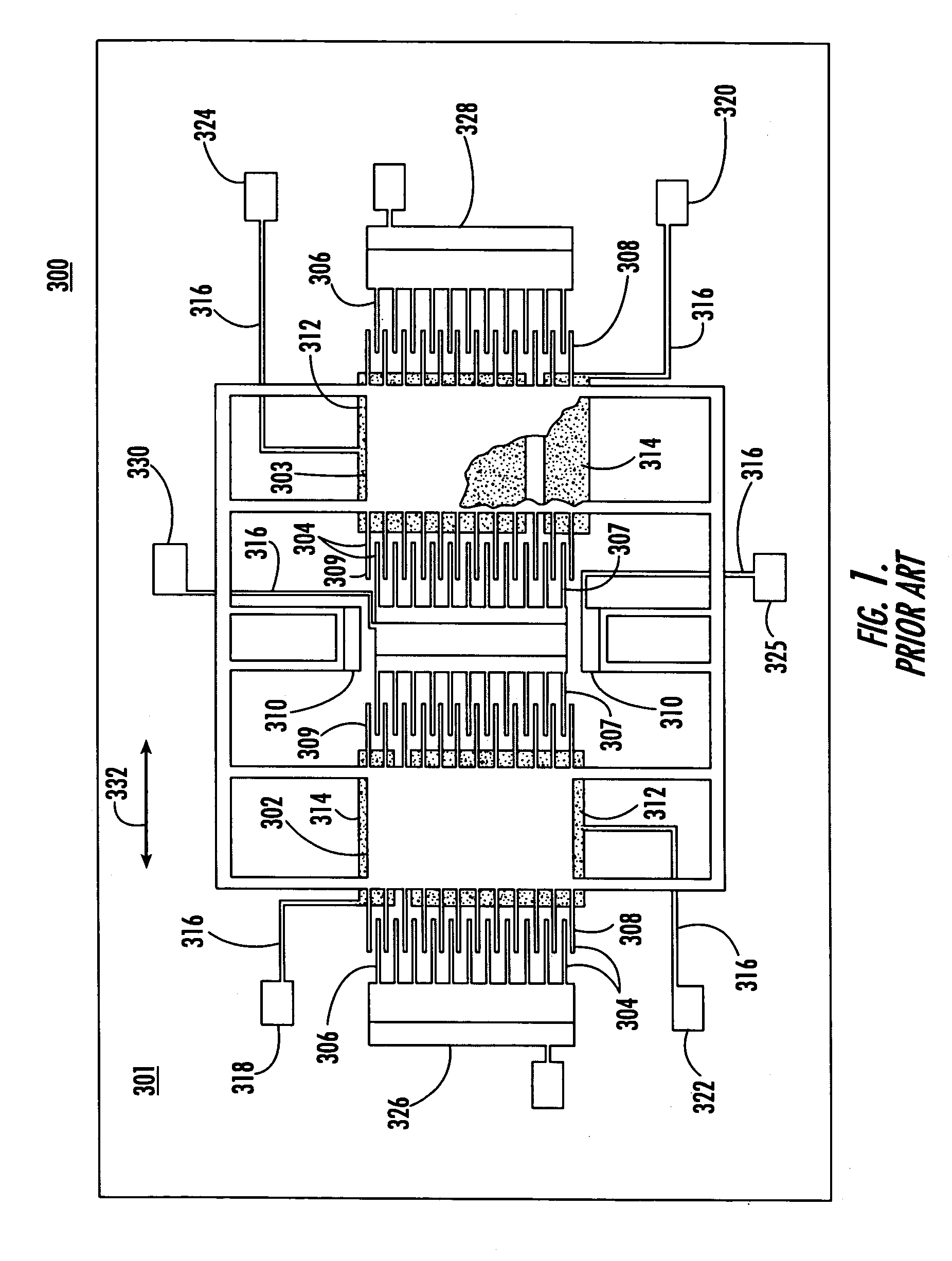
[0047]Prior art tuning fork gyroscope 300, FIG. 1, is also known in the art as a comb drive gyroscope. Gyroscope 300 includes vibrating or proof masses 302 and 303. Interleaved fingers 304, including outer comb drive fingers 306, 307 and inner comb driven fingers 308, 309 impart vibrational motion to vibrating masses 302, 303. The sensed motion is wired to electronics (not shown) that generate the driving voltage so that a self-oscillator is realized. It is known to reverse the role of inner and outer combs. Both solid and horizontally and vertically split inner combs have been used although horizontal splits in both the inner and outer combs are now preferred. Vibrating masses 302, 303 are suspended relative to lower substrate 301 by one or more anchors 310. Sense plates or electrodes 312, 313 and torque electrodes 314 are disposed only beneath a portion of each vibrating mass 302, 303. A plurality of conductive leads 316 interconnect right torque transducer 318, left torque transd...


PUM


Abstract

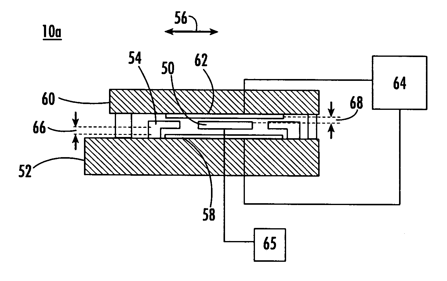
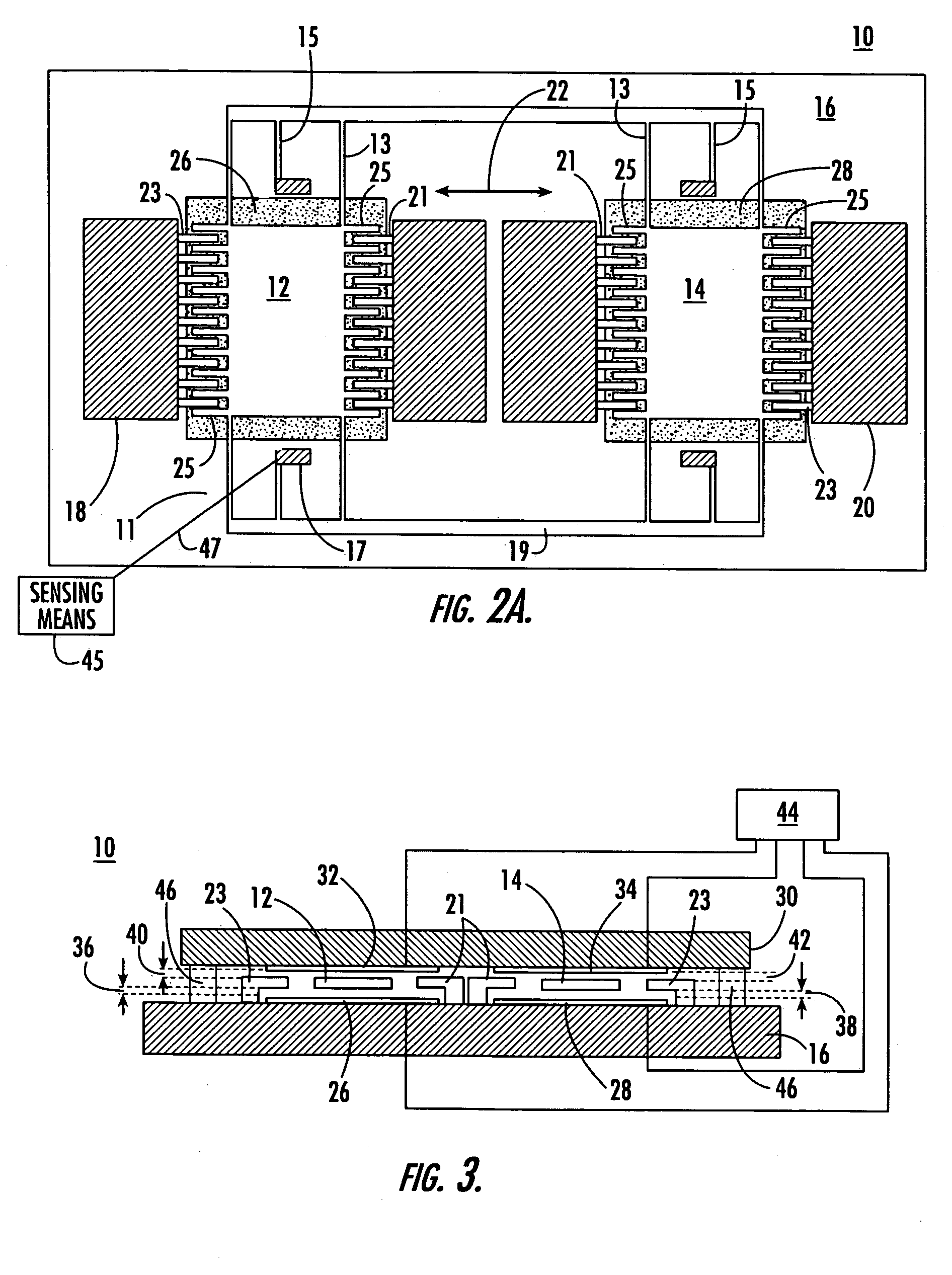
A method for reducing errors in a tuning fork gyroscope includes determining a first distance, gt, between an upper sense plate and a proof mass and a second distance, gb, between a lower sense plate and the proof mass. The method further includes applying a first voltage, Vt, to the upper sense plate and a second voltage, Vb, to the lower sense plate, wherein the ratio of the first voltage and the second voltage is a function of the first distance and the second distance.

Description

RELATED APPLICATIONS[0001]This application is a divisional of U.S. patent application Ser. No. 10 / 264,887 filed Oct. 4, 2002 now U.S. Pat. 6,862,934 entitled TUNING FORK GYROSCOPE which claims the benefit of and priority to U.S. Provisional Application Ser. No. 60 / 327,450 filed Oct. 5, 2001 and U.S. Provisional Application Ser. No. 60 / 327,434 filed on Oct. 5, 2001 and which is a Continuation-in-Part of U.S. application Ser. No. 10 / 004,145 filed Oct. 23, 2001 now U.S. Pat. 6,548,321entitled METHOD OF ANODICALLY BONDING A MULTI-LAYER DEVICE WITH A FREE MASS, each of which are incorporated herein by reference.FIELD OF THE INVENTION[0002]This invention relates to a tuning fork gyroscope.BACKGROUND OF THE INVENTION[0003]Tuning fork gyroscopes are used to sense angular displacement in military and commercial (e.g., automotive) environments. In one design, two silicon proof masses (vibrating elements) are suspended above a silicon or glass substrate (or a glass substrate with a silicon lay...

Claims


Application Information

Patent Timeline
Patent Type & Authority Patents(United States)
IPC IPC(8): H01L21/00B81B3/00B81C1/00G01C19/5719H01L21/683
CPCG01C19/5719H01L21/6835H01L2924/3025H01L2924/30105H01L2924/19041
Inventor WEINBERG, MARC S.KOUREPENIS, ANTHONY S.SAWYER, WILLIAM D.BORENSTEIN, JEFFREY T.CONNELLY, JAMES H.DUWEL, AMY E.LENTO, CHRISTOPHER M.COUSENS, JAMES R.
Owner CHARLES STARK DRAPER LABORATORY
Learn More