

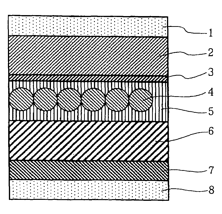
Electroluminescence device having phosphor particles which give donor-acceptor type luminescence
a technology of phosphor particles and luminescence, which is applied in the direction of discharge tube/lamp details, discharge tube luminescence screens, other domestic articles, etc., can solve the problems of low luminance and efficiency, no generation format wherein nucleus formation and growth can be taken
- Summary
- Abstract
- Description
- Claims
- Application Information
AI Technical Summary
Problems solved by technology
Method used
Image

Examples
example 1
1) Preparation of Zinc Sulfide Fine Particles
[0071]To 25 g of ZnS particle powder having an average particle diameter of 20 nm was added 5 g of MgCl2 as a flux, thereto were added magnesium oxide, potassium iodide, aluminum oxide powder, each in a desired amount, as a flux, to control particle diameter; and further thereto was added copper sulfate in an amount of 0.07 mol % based on ZnS. The resultant dry powder was put into a crucible made of alumina, fired at 1250° C. for 1 hour, and then rapidly cooled. Thereafter, the powder was taken out and then pulverized in a ball mill. The resultant was further added with water to solate, followed by ultrasonic dispersion. Thereto were added ZnCl2 in an amount of 5 g and copper sulfate in an amount of 0.10 mol % based on ZnS. Thereafter, 1 g of MgCl2 was added thereto, to-prepare a dry powder. Again, the powder was put into an alumina crucible and fired at 700° C. for 2 hours. The firing was conducted while 10% hydrogen sulfide gas as an at...
example 2
[0086]To a closed-type reaction kettle heated to 300° C. were added 0.6 M of sodium sulfide aqueous solution and 0.6 M of zinc nitrate aqueous solution at an addition rate of 0.01 mole per minute over one hour. In advance of this process, 1 liter of a 0.6 M NaCl solution was prepared in the reaction kettle. Sulfuric acid was used to adjust the pH of the solution to 2 or less. After pH was adjusted, a solution of copper sulfate was quantitatively added to the solution at a rate of 0.1 mole % based on zinc. In this way, particles were prepared, to yield Particles C-1 having an average particle diameter of 3.0 μm and a coefficient of variation of 24%. Particles C-2 to C-6 were prepared in the same manner as particles C-1, except that the following conditions were changed: the concentration of NaCl, the temperature, the rate of the addition, the pH, and the excessive amount of sodium sulfide added in the reaction kettle in advance. Characteristics of the respective particles are shown i...
example 3
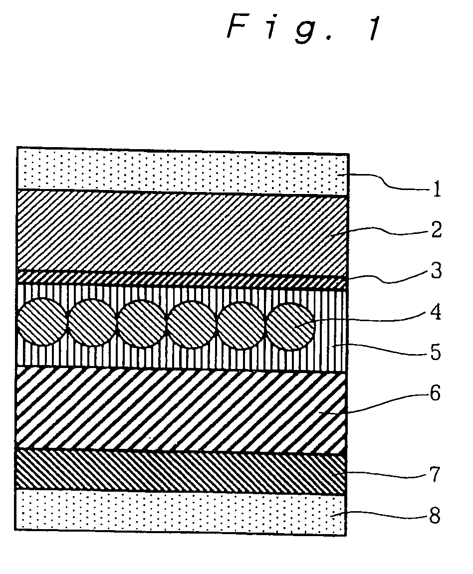
[0091]The Particles C-5 according to the present invention, produced in Example 2, were used as seed crystals, and each of the particles was provided with a zinc sulfide shell of a thickness of 0.25 μm. The thus-prepared particles had an average sphere diameter of 2.5 μm with the coefficient of variation thereof of 21%. An electroluminescence device was prepared in the same manner as Device D-5 in Example 2, except for using the thus-obtained particles. The luminance thereof was measured. The relative luminance thereof was 400.
PUM
| Property | Measurement | Unit |
|---|---|---|
| diameters | aaaaa | aaaaa |
| diameters | aaaaa | aaaaa |
| thickness | aaaaa | aaaaa |
Abstract
Description
Claims
Application Information