Emplacement of treatment agents using soil fracturing for remediation of subsurface environmental contamination
a technology of soil fracturing and treatment agents, applied in the direction of biological water/sewage treatment, sealing/packing, borehole/well accessories, etc., can solve the problem that compounding often presents unique obstacles
- Summary
- Abstract
- Description
- Claims
- Application Information
AI Technical Summary
Benefits of technology
Problems solved by technology
Method used
Image
Examples
example 1
[0050]Site Background. The Distler Brickyard Site (located outside Louisville, Ky.) contains the chlorinated aliphatic hydrocarbon (CAH) TCE at concentrations above the maximum contaminant level in groundwater. The presence of reducing conditions and less chlorinated degradation products cis-1,2-dichloroethene (cis-1,2-DCE), vinyl chloride (VC), and ethene indicated that biodegradation via anaerobic reductive dechlorination (ARD) was occurring naturally in the system. However, the rate and extent of ARD appeared to be limited by a lack of available electron donor. For this reason, a remediation technology that enhanced natural ARD via electron donor addition was hypothesized to be a viable method for reducing CAH concentrations to acceptable levels.
[0051]Remediation of CAHs at the Distler Site presented a number of challenges: (1) contamination was present in low permeability sediments, (2) the zone of contamination was variably saturated depending on seasonal changes in precipitati...
example 2
[0061]Methods. Laboratory testing was performed to determine the actual carrying capacity of a fracture slurry comprising 20–40 mesh size chitin and 20–40 API specification frac sand. Blender stall, gelation, and specific gravity testing were performed using several guars and enzyme breaker over a range of pH values until a maximum concentration of pumpable chitin and sand was determined. The basic procedure comprised adding incremental amounts of chitin to the sand slurry in a blender until the solution caused the blender to stall. Based on previous research performed by Vanson HaloSource, Inc. (Redmond, Wash.), chitin was expected to be compatible with the guar slurry. For this reason, no additional compatibility testing studies were performed.
[0062]Results and Discussion. Previous laboratory testing conducted by Vanson indicated that chitin / guar mixtures are compatible and that chitin will not interfere with the functionality of the guar gel. Subsequent laboratory studies indicat...
example 3
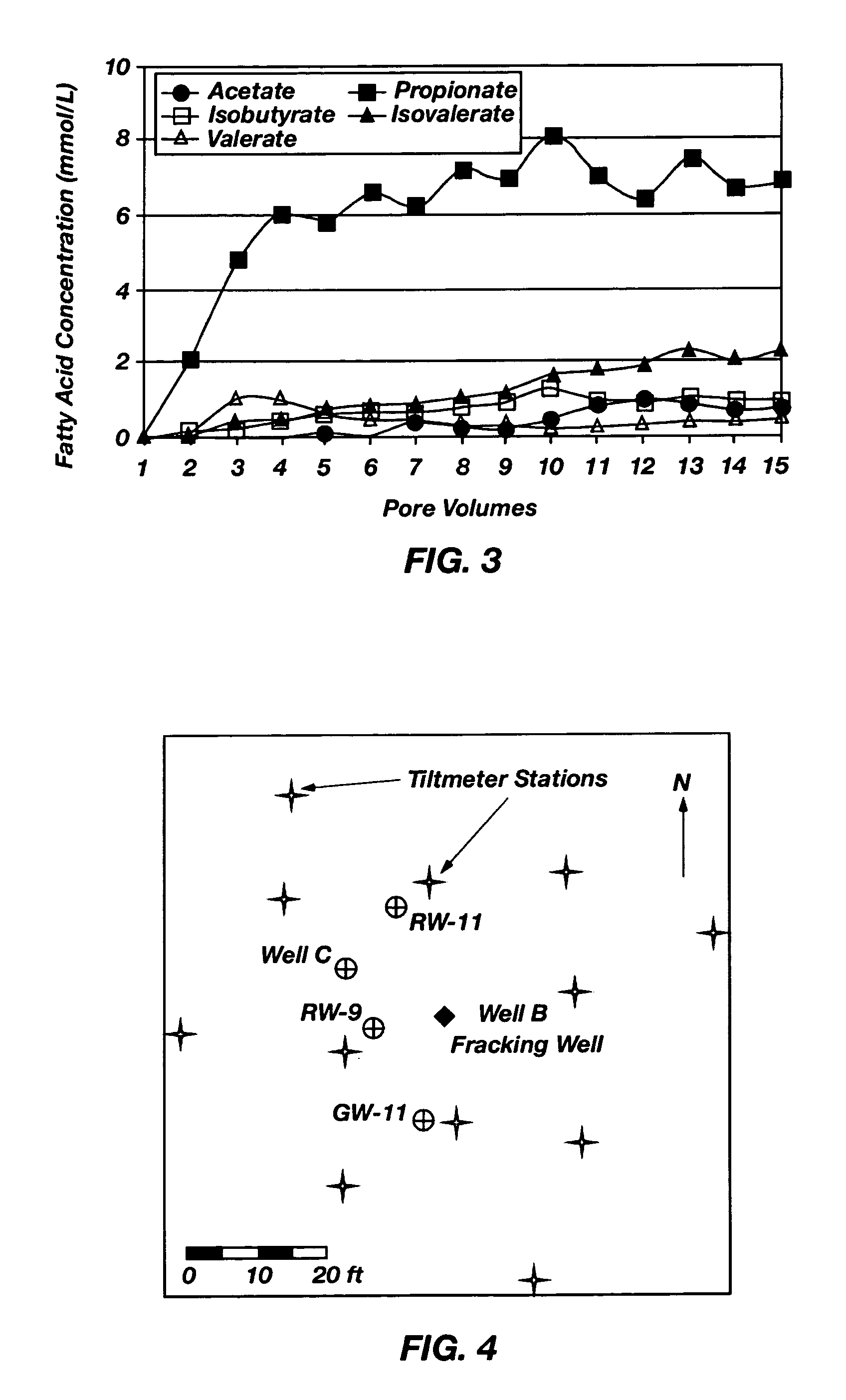
[0065]Methods. A field test was designed and conducted in the suspected CAH source area (FIG. 4) to determine if chitin could be emplaced into a low permeability formation using the present process. The location of the pilot test was moved from the original location down gradient of the source area to the source area due to higher water levels observed in the source area at the time of the monitoring well installation. The basic components of the field test comprised the following: (1) well installation, (2) pre-fracturing slug testing, (3) pre-fracturing baseline sampling, (4) fracturing and chitin emplacement, (5) tiltmeter monitoring during fracturing, (6) post-fracturing slug testing, (7) pumping test, and (8) post-fracturing monthly groundwater monitoring.
[0066]Hydraulic fracturing and chitin emplacement were conducted in a single well, Well B, which was drilled as part of the fracturing activity (FIG. 4). Three fracture zones were created at the following depths below ground s...
PUM
| Property | Measurement | Unit |
|---|---|---|
| retention time | aaaaa | aaaaa |
| retention time | aaaaa | aaaaa |
| retention time | aaaaa | aaaaa |
Abstract
Description
Claims
Application Information
 - R&D
- Intellectual Property
- Life Sciences
- Materials
- Tech Scout
- Unparalleled Data Quality
- Higher Quality Content
- 60% Fewer Hallucinations
Browse by: Latest US Patents, China's latest patents, Technical Efficacy Thesaurus, Application Domain, Technology Topic, Popular Technical Reports.
© 2025 PatSnap. All rights reserved.Legal|Privacy policy|Modern Slavery Act Transparency Statement|Sitemap|About US| Contact US: help@patsnap.com


