Antenna with built-in filter

a filter and built-in technology, applied in the structure of resonant antennas, multiple-port networks, radiating elements, etc., can solve the problems of increased high-frequency resistance or inductance, increased transmission signal loss or damping characteristic, and low shielding effect in the surface direction of multi-layer structures. , to achieve the effect of low resistance and simple structur

Inactive Publication Date: 2007-02-20
YOKOWO CO LTD +1
View PDF23 Cites 45 Cited by
  • Summary
  • Abstract
  • Description
  • Claims
  • Application Information

AI Technical Summary

Benefits of technology

[0032]One antenna element is folded so that at least two portions in which adjacent elements are electrically coupled respectively are formed, the radiation electrode is formed from the antenna element so as to resonate in the desired four frequency bands by adjusting the electrically coupled portion and so that one end of the antenna element is connected to filters of the respective frequency bands through a multiplexer. As a result, the one radiation electrode is provided for four frequency bands of cellular, GPS and BT, thereby to miniaturize it with further simple structure.
[0033]The dielectric multilayer structure according to the present invention is the dielectric multilayer structure in which the plural dielectric sheets each having an electroconductive

Problems solved by technology

However, a signal transmission path is locally narrowed in the connection using the through-hole, which increases high-frequency resistance or inductance and comes to increase in transmission signal loss or decline in the damping characteristic.
Although the structure can be shielded in the vertical direction by providing an earth conductor film on the ceramic sheet, the shielding is not effective in the surface direction of the multilayer structure (in the direction parallel to the ceramic sheet) because an electric wave is leaked laterally from a gap of the connecting parts of the through-hole.
However, since further miniaturization is demanded in the portable device, to provide the antennas at various places in the portable device is contrary to the demand for the miniaturization.
As described above, according to the conventional antenna with a built-in filter, since the antenna and the band pass filter are connected through the connector and connection cable, the device becomes large and loss is increased.
In addition, since the radiation element and the filter separately function, it is necessary to match the impedance of the radiation element, which furthe

Method used


Image

  • Antenna with built-in filter
  • Antenna with built-in filter
  • Antenna with built-in filter

Examples


Embodiment Construction

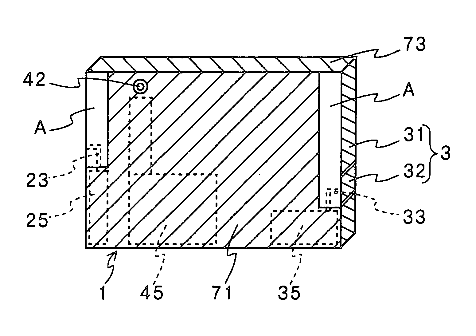
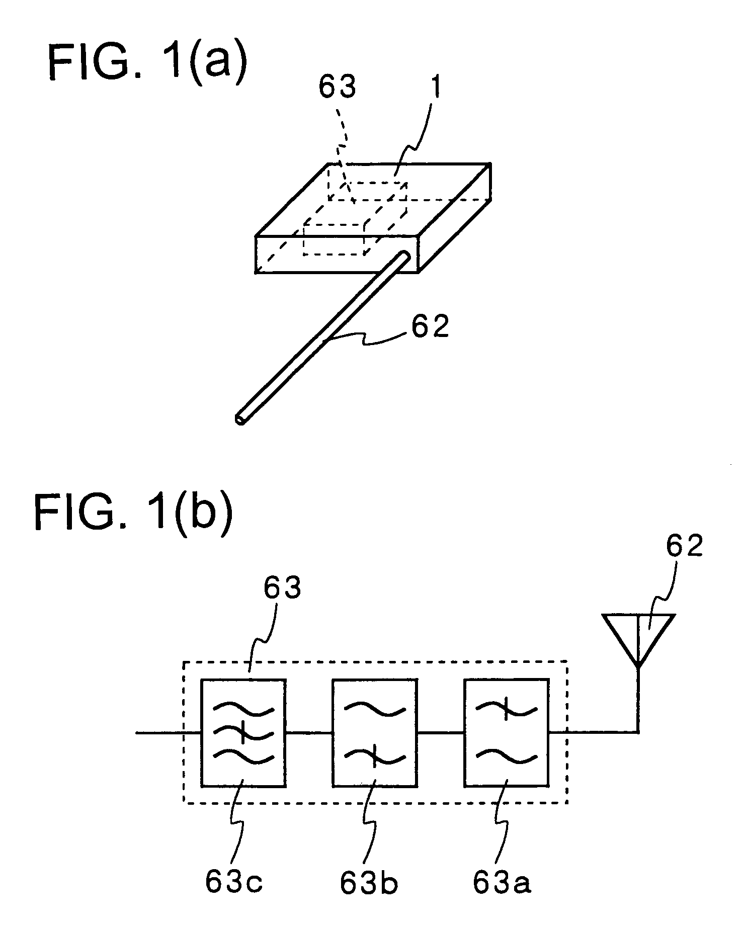
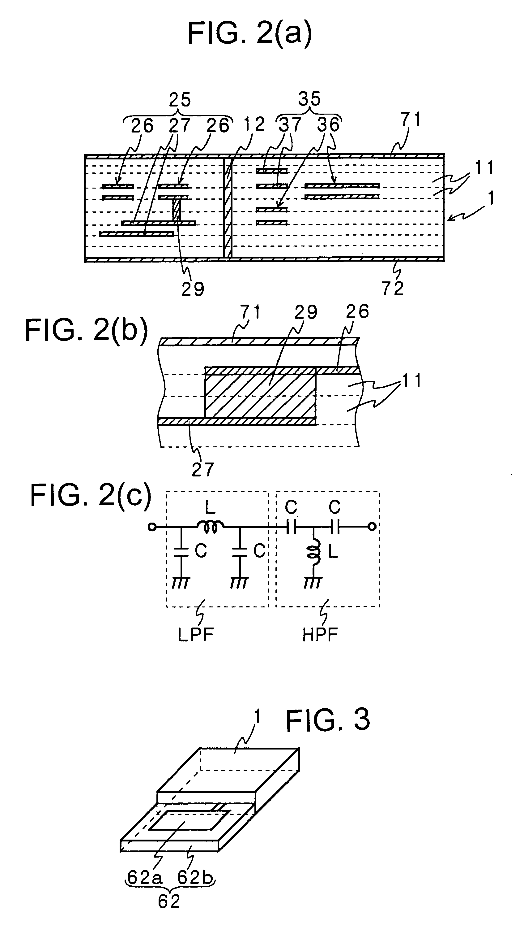
[0045]Then, an antenna with a built-in filter according to the present invention will be described with reference to the drawings. According to the antenna with a built-in filter of an embodiment of the present invention, as a structural view and a block diagram there of is shown in FIG. 1, a dielectric multilayer structure 1 is constituted in such a manner that dielectric sheets 11 (referring to FIG. 2(a)) on which an electrodoncutive film is formed are laminated so as to constitute at least one filter block 63. A radiation element 62 is attached to the dielectric multilayer structure 1 and the radiation element 62 is connected to the filter block 63. The filter block 63 includes at least one of a low-pass filter 63a, a high-pass filter 63b and band-elimination filter 63c. Although only one radiation element 62 and one filter block 63 are shown in FIG. 1, as described above, a plurality of radiation elements and a plurality of filter blocks 63 may be attached to or built in the die...


PUM


Abstract

At least one filter block (25, 35, 45) is formed in a thin and flat dielectric multilayer structure (21) and fixed with radiation elements (2, 3). Each filter block includes at least one of a low-pass filter, a high-pass filter and a band-eliminating filter. On the surface (one major surface) side and/or the side face of the multilayer structure, at least one radiation element (2, 3) being connected with the filter block is provided and feeding parts (28, 38, 48) for supplying signal to the radiation elements are provided on the rear surface of the multilayer structure. Consequently, the antenna and the filter block are integrated and a small surface mountable antenna with a built-in filter of a structure such that signals are not mixed each other even when signals of a plurality of frequency bands are transmitted/received can be obtained.

Description

[0001]This application is the National Phase of International Application PCT / JP02 / 01637 filed Feb. 22, 2002.TECHNICAL FIELD[0002]The present invention relates to an antenna with a built-in filter which has a filter having a superior separating function so as not to generate a noise on another signal because of reciprocal interference even when a plurality of frequency bands are transmitted or received at the same time, and which is small in size so as to be suitable for being mounted on a portable telephone, a personal digital assistant or the like, and in which matching is easy. More particularly, it relates to an antenna with a built-in filter having a compact structure in which reciprocal interference will not occur even if it is constituted such that signals of a plurality of frequency bands such as cellular and GPS or Bluetooth can be transmitted or received by one block of antenna.BACKGROUND ART[0003]Conventionally, signals transmitted or received by an antenna pass through a...

Claims


Application Information

Patent Timeline
IPC IPC(8): H01Q15/02H01Q1/24H01Q1/38H01Q5/00H01Q5/35H01Q5/50H01Q9/04H01Q23/00H03H7/01
CPCH01Q1/243H01Q1/38H01Q9/0442H01Q5/50H03H7/0115H01Q5/35H01Q23/00H03H2001/0085H01Q1/24
Inventor HORIE, RYOSUZUKI, MITSUHIROKAMEDA, SHOZABUROFUKUDA, KOICHIICHIKAWA, HIROSHIOYAMA, RYUJI
Owner YOKOWO CO LTD
Why Eureka
Try Eureka