Structural printing of absorbent webs

Inactive Publication Date: 2007-02-27
KIMBERLY-CLARK WORLDWIDE INC
View PDF106 Cites 69 Cited by
  • Summary
  • Abstract
  • Description
  • Claims
  • Application Information

AI Technical Summary

Benefits of technology

[0038]A suitable method for measurement of Surface Depth is moiré interferometry which permits accurate measurement without deformation of the surface of the tissue webs. For reference to the tissue webs of the present invention, the surface topography of the tissue webs should be measured using a computer-controlled white-light field-shifted moiré interferometer with about a 38 mm field of view. A suitable commercial instrument for moiré interferometry is the CADEYES® interferometer produced by Integral Vision (Farmington Hills, Mich.), constructed for a 38-mm field-of-view (a field of view within the range of 37 to 39.5 mm is adequate). The CADEYES® system uses white light which is projected through a grid to project fine black lines onto the sample surface. The surface is viewed through a similar grid, creating moiré fringes that are viewed by a CCD camera. Suitable lenses and a stepper motor adjust the optical configuration for field shifting. A video processor sends captured fringe images to a PC computer for processing, allowing details of surface height to be back calculated from the fringe patterns viewed by the video camera.
[0039]The computerized CADEYES® interferometer system is used to acquire topographical data and then to generate a grayscale image of the topographical data, said image to be hereinafter called “the height map”. The height map is displayed on a computer monitor, typically in 256 shades of gray and is quantitatively based on the topographical data obtained for the sample being measured. The resulting height map for a 38-mm square measurement area shou

Problems solved by technology

When wetted, however, the fibers may swell and straighten as the local stresses associated with the kinks or microcompressions in the fiber relax.
Thus, embossed tissue when wetted tends to lose much of the added bulk imparted by embossing, and tends to collapse back to a relatively flat state.
These methods, however, do little to protect the t

Method used


Image

  • Structural printing of absorbent webs
  • Structural printing of absorbent webs
  • Structural printing of absorbent webs

Examples


Example

EXAMPLE 1

[0179]To demonstrate the potential for flexographic printing to transfer substantial quantities of a high solids, high-viscosity adhesive material to a paper surface, a reel of commercial coated printing paper was flexographically printed with a hot melt adhesive using the heated flexographic printing equipment of Propheteer International (Lake Zurich, Ill.). The Propheteer 2000 3-Color line was used, comprising an unwind unit, a UV curing station, a flexographic hot melt applicator, a rewind unit, a sheeting station and a stacker. The flexographic applicator was a Flexo Hot Melt Applications Processor manufactured by GRE Engineering Products AG in Steinebrunn, Switzerland (believed to be GRE model HM 220–500). It was adapted to process sheets up to 20 inches wide. The flexographic plate comprised a high-temperature silicone elastomer having a maximum application temperature of 500° F. based on polydimethylsiloxane produced by the Chase Elastomer Division of PolyOne Corpora...

Example

EXAMPLE 2

[0194]Both hotmelts described in Example 1 were printed with two different patterns according to Example 1, but on a high bulk, resilient, three-dimensional uncreped through-dried web.

[0195]The uncreped web was formed in a similar method to that disclosed in Example 1 of U.S. Pat. No. 6,395,957 to Chen, et al. (herein incorporated by reference as to all relevant matter). The base sheet was produced on a continuous tissue-making machine adapted for uncreped through-air drying, similar to the machine configuration shown in FIG. 4 of Chen, et al. The machine comprised a Fourdrinier forming section, a transfer section, a through-drying section, a subsequent transfer section and a reel.

[0196]The process included a three-layered headbox to form a web with three layers. The two outer layers in the three-layered headbox comprised dilute pulp slurry (about 1% consistency) made from LL19 pulp, a southern softwood bleached kraft pulp of Kimberly-Clark Corp., (Dallas, Tex.). The centr...

Example

EXAMPLE 3

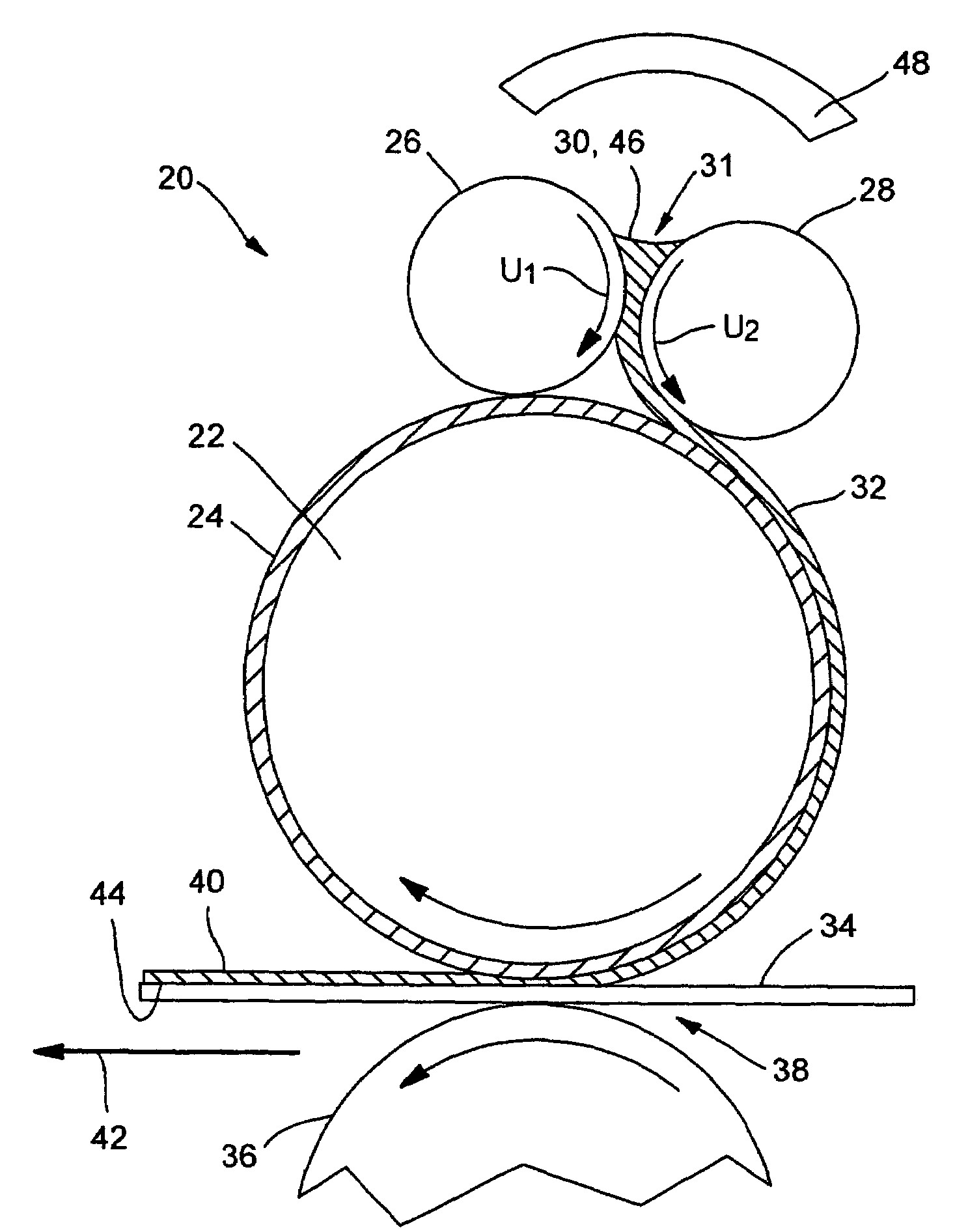
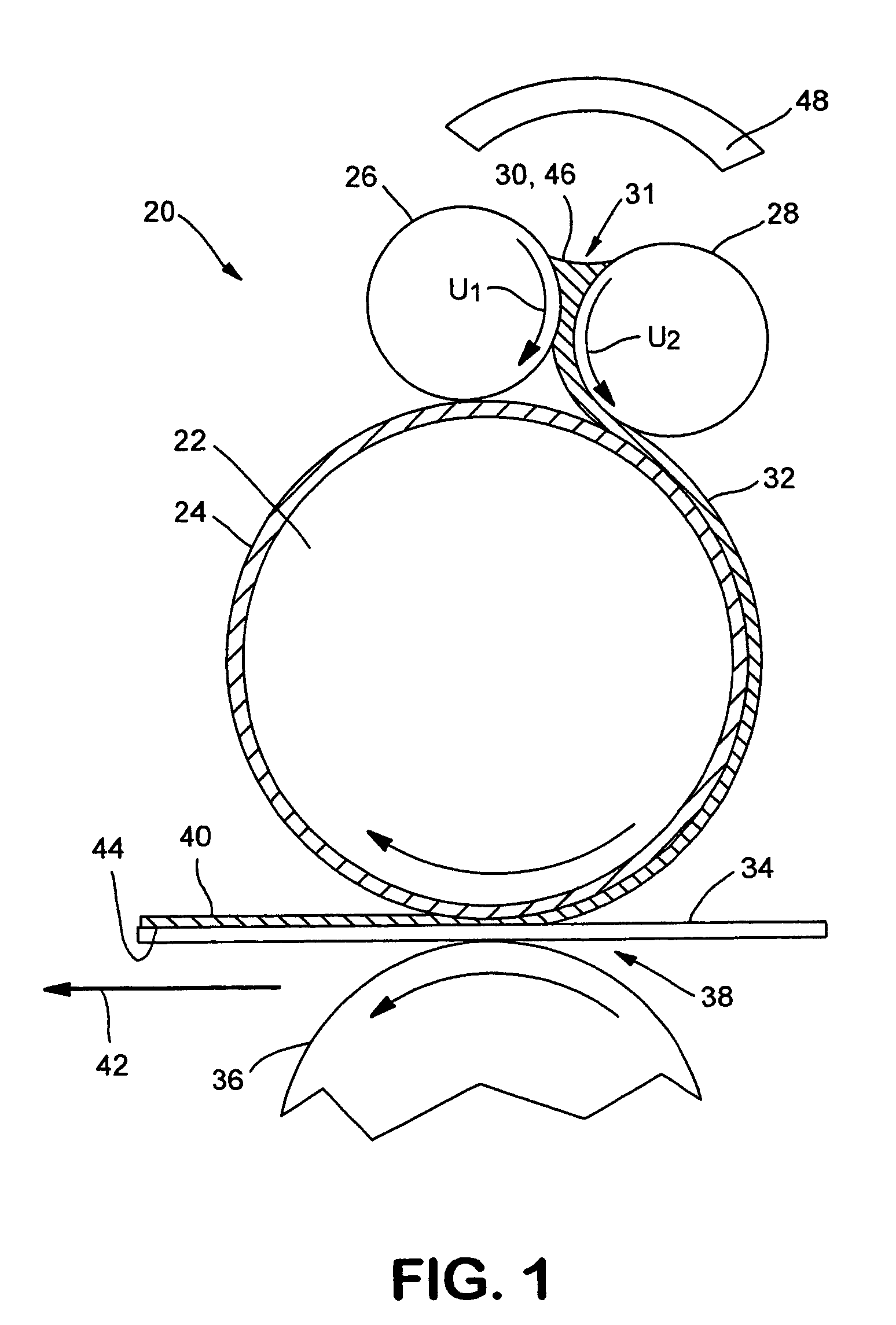
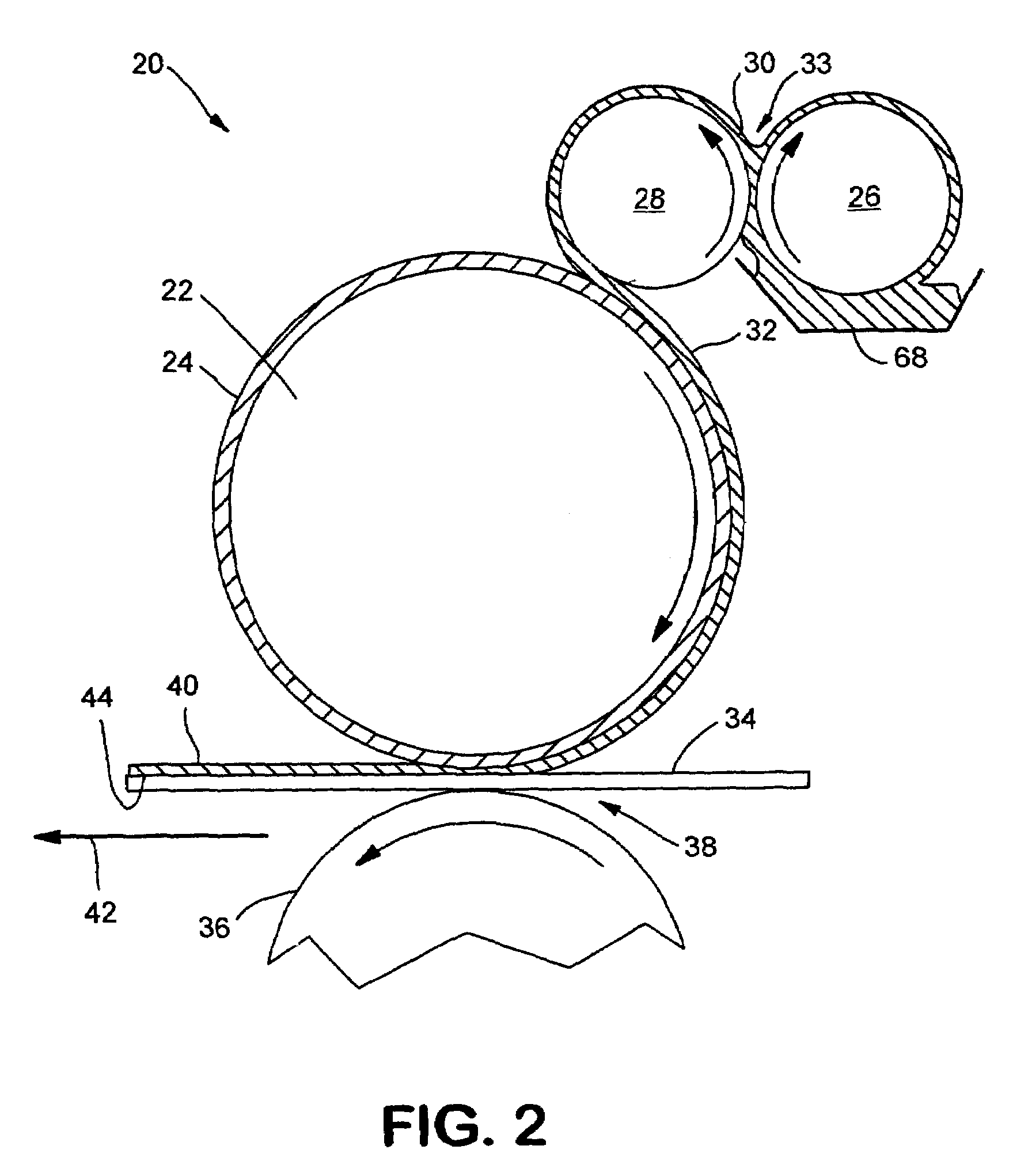
[0199]To demonstrate flexographic printing of a synthetic latex emulsion, runs were conducted on a Kimberly-Clark pilot printing facility in Neenah, Wis. A four-roll flexographic system, substantially as shown in FIG. 13, was used, but typically with adhesive applied on one side only. The flexographic system was manufactured by Retroflex, Inc. of Wrightstown, Wis. Flexographic plates were prepared with the three patterns shown in FIGS. 14A–14C.

[0200]A roll of the unprinted, uncreped through-air dried tissue made according to Example 2 was positioned in an unwind stand from which it was guided through the flexographic press. The flexographic printer was configured for single side application with a gap offset of 0.003″ inch. Printed latex was dried as the web passed through an infrared oven set at 380° F. (not shown in FIG. 13). The web with the dried latex was then wound into a roll. The unwind, flexographic printing system, oven drying and curing and rewind units were syn...


PUM

PropertyMeasurementUnit
Pressureaaaaaaaaaa
Pressureaaaaaaaaaa
Pressureaaaaaaaaaa

Abstract

A process and method which ‘locks in’ three-dimensional texturing added to a paper web by virtue of an adhesive material which is printed onto the surface of the web is generally disclosed. The adhesive may be applied to the web either before, during, or after the web is molded to increase the surface texture. The adhesive may be applied at relatively low pressure so as to preserve surface texture without significant deformation of the web. The cured adhesive material inhibits the web from reassuming a two-dimensional state or may contribute additional texture by rising above the surface of the web. This process may not only increase the bulk of the web when dry and wet, but also increase the wet resiliency, the wet strength, and the tactile properties of the web.

Description

BACKGROUND OF THE INVENTION[0001]Products made from paper webs such as bath tissues, facial tissues, paper towels, industrial wipers, food service wipers, napkins, medical pads and other similar products are designed to include several important properties. For example, the product should have a relatively soft feel and, for most applications, should be highly absorbent. High bulk is also often preferred in such products. For example, three dimensional, high bulk paper products are often preferred over thinner, more two-dimensional products.[0002]Several methods have been proposed in the past for imparting three-dimensional structures to a fibrous paper web. One well-known method is embossing, wherein the fibers in the web are mechanically deformed under high mechanical pressure to impart kinks and microcompressions in the fibers that remain substantially permanent while the web is dry. When wetted, however, the fibers may swell and straighten as the local stresses associated with t...

Claims


Application Information

Patent Timeline
IPC IPC(8): D21H23/56B05C1/08B05C1/16B41M1/24B41M3/00B41M3/18
CPCB05C1/165B41M1/24B05C1/083B05C1/0834Y10T428/24455B41M3/00Y10T428/24479B41M1/04D21H23/56
Inventor CHEN, FUNG-JOULINDSAY, JEFFREY D.HUNT, THOMAS F.TIRIMACCO, MAURIZIOURLAUB, JOHN J.
Owner KIMBERLY-CLARK WORLDWIDE INC
Why Eureka
Try Eureka