Method and apparatus for fiber Bragg grating production

a fiber bragg grating and production method technology, applied in the field of optical waveguide manufacturing, can solve the problems of high operating and maintenance costs, and current sources of ultraviolet light used in fbg production

Active Publication Date: 2007-02-27
LOCKHEED MARTIN CORP
View PDF13 Cites 46 Cited by
  • Summary
  • Abstract
  • Description
  • Claims
  • Application Information

AI Technical Summary

Benefits of technology

[0010]In order to address the shortcomings in prior art devices for making FBG's, the present invention discloses a variety of solid state lasers which generate moderate peak-power radiation at wavelengths suitable for FBG production. These lasers are used in combination with various devices for producing FBG's at a rate which exceeds that of current production devices. Moreover, the FBG's are produced without significant damage to the fibers, without exposing workers and equipment to toxic and corrosive gases and without the frequent maintenance required for other FBG systems.

Problems solved by technology

Unfortunately, the current sources of ultraviolet light used for FBG production have various drawbacks.
KrF excimer lasers can produce high average powers, which facilitates processing, but they have serious disadvantages.
They require toxic, corrosive gases for operation, have high operating and maintenance costs, and produce short duration (˜50 ns), low repetition rate (<1000 Hz), high peak output power (˜1 MW) ultraviolet pulses.
The high peak output powers cause damage to the fibers, weakening them and making them susceptible to fracture.
The alternative continuous wave (“cw”) argon ion lasers suffer high operating costs and produce weak output powers of one-half watt or less, leading to poor production throughput.
However, the argon-fluoride and xenon-chloride excimer lasers suffer from disadvantages similar to those of KrF excimer lasers.
Flashlamp-pumped lasers provide some operational improvements compared to excimer lasers, but also generate high peak power pulses which damage the optical fibers.
Frequency-doubled liquid dye lasers have been tuned to the 240 nm region for FBG fabrication, but such lasers are impractical for large-scale industrial production, since they require very frequent changes of the liquid dye solution to maintain operation.
Solid state lasers would be of great interest for FBG production, but heretofore have not been usable because they have not been able to produce the required wavelengths.

Method used


Image

  • Method and apparatus for fiber Bragg grating production
  • Method and apparatus for fiber Bragg grating production
  • Method and apparatus for fiber Bragg grating production

Examples


Embodiment Construction

[0036]A. Fabrication of Bragg Gratings

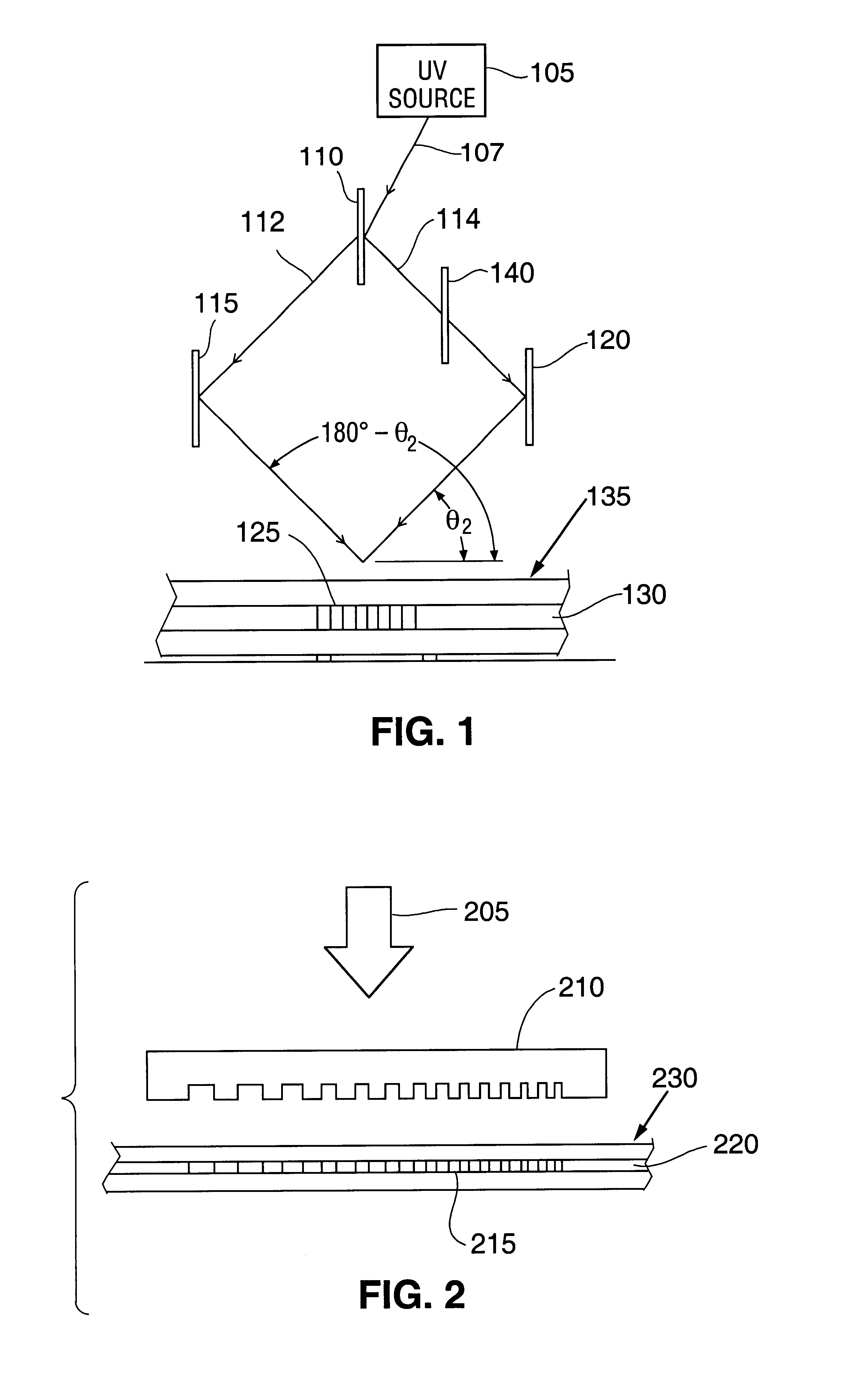
[0037]There are two basic methods of generating the necessary alternating light and dark regions of an FBG, with many variations of each method. The first is a “holographic” method, wherein two ultraviolet beams are caused to interfere with one another. The resulting interference pattern is projected onto the germanium-doped portion of the fiber. The second basic method is noninterferometric and involves exposure of the fiber to periodic ultraviolet (“UV”) radiation.

1. Holographic Methods

[0038]A basic holographic method is shown schematically in FIG. 1. There, ultraviolet source 105 (typically some form of laser) generates beam 107, which is split into beams 112 and 114 by beam splitter 110. For low-coherence sources, it is advantageous to equalize the path lengths of beams 112 and 114. InFIG. 1, these path lengths are equalized by disposing compensating plate 140 in the path of beam 114. Beams 112 and 114 reflect from mirrors 115 and 120, respe...


PUM

PropertyMeasurementUnit
wavelengthaaaaaaaaaa
wavelengthsaaaaaaaaaa

Abstract

Fiber Bragg writing devices comprising solid state lasers are provided. The solid state lasers comprise optical parametric oscillators and emit moderate peak-power output beams at wavelengths which are suitable for efficient production of fiber Bragg gratings without causing embrittlement of the optical waveguide. These solid state lasers generate output beams with wavelengths of approximately 240 nm, in order to match the primary absorption peak in the ultraviolet range for a typical optical waveguide. Some of these solid state lasers generate tunable wavelength beams using an optical parametric oscillator (“OPO”), then generate harmonics of these tunable beams. Other lasers mix the tunable beam with fixed wavelengths derived from the pump laser to reach the desired output wavelength.

Description

CROSS-REFERENCES TO RELATED APPLICATIONS[0001]This application claims priority based on the following U.S. Provisional Patent Application Ser. Nos., the disclosures of which are incorporated herein by reference for all purposes: 60 / 249,989, filed Nov. 20, 2000; 60 / 269,150, filed Feb. 15, 2001; 60 / 269,152, filed Feb. 15, 2001; and 60 / 276,651, filed Mar. 16, 2001.FIELD OF THE INVENTION[0002]The invention relates generally to the field of optical waveguide manufacturing and particularly to the processing of optical fibers to create fiber Bragg gratings.BACKGROUND OF THE INVENTION[0003]Fiber Bragg gratings (FBG's) are portions of optical waveguides, such as optical fibers, which have been processed to reflect and transmit specific wavelengths. The waveguides are typically germanium-doped silica fibers and for the purposes of this description will be referred to as “fibers” or “optical fibers.” However, it should be understood that these terms are being used in a generic sense to mean an...

Claims


Application Information

Patent Timeline
Patent Type & Authority Patents(United States)
IPC IPC(8): G02F1/295G02B6/02G02B6/12G02B6/124G02F1/35G02F1/37H01S3/067H01S3/117H01S5/14
CPCG02B6/02133G02B6/02138G02B6/124G02F1/353G02B2006/12107H01S5/146G02F2001/3507G02F2001/354G02F2201/16H01S3/0675H01S3/117G02F1/37G02F1/3507G02F1/354
Inventor MEAD, ROY M.MIYAKE, CHARLES I.
Owner LOCKHEED MARTIN CORP
Why Eureka
Try Eureka