Product irradiator for optimizing dose uniformity in products

a product irradiator and product technology, applied in the direction of irradiation devices, instruments, material analysis through optical means, etc., can solve the problems of not meeting the required dose, prone to overexposure to radiation, and sensitive to product variations in radiation processing

Inactive Publication Date: 2007-03-06
MDS CANADA
View PDF17 Cites 26 Cited by
  • Summary
  • Abstract
  • Description
  • Claims
  • Application Information

AI Technical Summary

Problems solved by technology

One common problem in the radiation processing of products is that the effectiveness of radiation processing is sensitive to variations in product density and geometry, and product source geometry.
If a radiation chamber is loaded with totes comprising products with a range of densities and geometries,certain products will tend to be over-exposed to the radiation, while others do not achieved the required dose, especially within the central regions of the product.
However, this is not always possible as some product package configurations are not compatible with achieving a good dose uniformity when irradiation is carried out in the conventional manner.
In treatment of these products, an application of an effective radiation dose to reduce pathogens at the centre of the stack is often limited by associated undesirable sensory or other changes in the periphery of the product stack as a result of the higher radiation dose delivered to material in this region of the product.
In these cases, the maximum permissible radiation dose in a product may be limited by undesirable changes in the characteristics of the plastics, such as increased embrittlement of polypropylene or decoloration and smell development of polyvinyl chloride.
A major drawback to electron beam processing, is that the electron beam is only capable of penetrating relatively shallow depths (i.e. cm) into product, especially high density products such as food stuffs.
This limitation reduces the effectiveness of electron beam processing of bulk or palletized materials of high density.
In the prior art systems described above, there are limitations in the ability to deliver a relatively flat dose distribution (low DUR) throughout a product or product stack since no method is provided to compensate for the different doses received by the exterior and interior portions of the product stack.
However, there is no guidance as to how this or the other shielding elements are to be positioned in order to attenuate the radiation beam relative to the product stack in order to optimize the DUR within the product.
Nor is there any discussion of any real-time adjustment of shielding elements to optimize the dose distribution received by a product that accounts for alterations in product densities.
A major limitation with the prior art irradiation systems is that it is difficult to obtain a relatively even radiation dose distribution (low DUR) throughout a product or product stack.
Even with systems that irradiate products from multiple sides, the material irradiated at the periphery of the product typically receives a higher dose of radiation than the material located at the centre of the product since the radiation method is not optimized for the product stacks.
Thus, prior art systems are limited in their ability to deliver a relatively flat dose distribution (low DUR) throughout a product or product stack.
These limitations are more pronounced in larger products, with higher densities.

Method used


Image

  • Product irradiator for optimizing dose uniformity in products
  • Product irradiator for optimizing dose uniformity in products
  • Product irradiator for optimizing dose uniformity in products

Examples


example 1

Radiation Profiles in a Product with Densities of about 0.2 or about 0.8 g / cm3

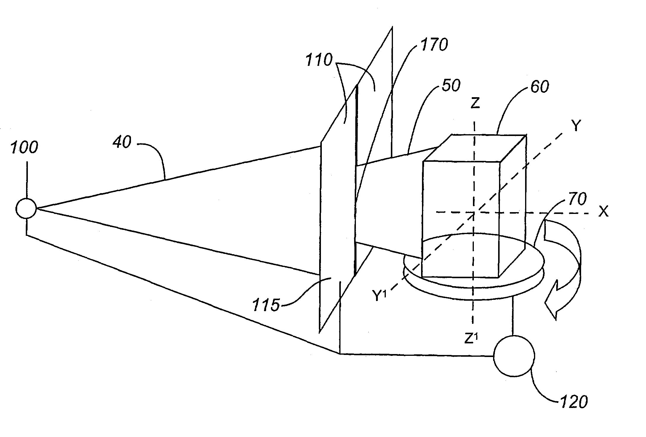
[0124]An accelerator capable of producing an electron beam of 200 kW and 5 MeV is used to, generate X-rays from a tungsten, water cooled converter. The bremsstrahlung energy spectrum of the X-ray beam produced in this manner extends from 0 to about 5 MeV, with a mean energy of about 0.715 MeV. A cylindrical product of 120 cm diameter, comprising a product with an average density of either 0.2 or 0.8 g / cm3 is placed onto a turntable that rotates at least once during the duration of exposure to the radiation beam. The distance from the source plane (converter) to the center of the product is 112 cm. The collimator is set to produce a beam width of 10, 50 or 120 cm. The rectangular cross section of height of the beam is set to the height of the product. Typically to deliver a dose of about 1.5 kGy to a product characterised in having a density of 0.2 g / cm3, the product is exposed to radiation for about 2 to ...

example 2

Irradiation of Circular and Rectangular Products: 1 mm Convertor

[0128]Bremsstrahlung X-rays are produced as described above using a 5 MeV electron beam with a circular cross section (10 mm diameter) that scanned vertically across the converter. A 1 mm Ta converter backed with an aluminum (0.5 cm) water (1 cm) aluminum (0.5 cm) cooling channel is used to generate the X-rays. A product of 0.8 g. / cm3, with two footprints are tested: one involved a cylindrical product with a 60 cm or 80 cm radius footprint, the other is a rectangular product with a footprint of 100×120 cm, and 180 cm height, both product geometries are rotated at least once during the exposure time. The distance from the converter to the collimator is 32 cm.

[0129]In order to optimize DUR, several collimator apertures are tested for a cylindrical product (Table 3). Examples of several determinations of the dose along a slice of the product, for a 60 cm radius cylindrical product are presented in FIG. 11.

[0130]

TABLE 3DUR ...

example 3

Irradiation of Circular and Rectangular Products: 2.35 mm Convertor

[0135]The Dmax:Dmin ratio may still be further optimized by increasing the overall penetration of the beam within the product. This may be achieved by increasing the thickness of the convertor to produce a X-ray beam with increased average photon energy. In order to balance yield of X-rays and beam energy, a Ta convertor of 2.35 mm (including a cooling channel; 0.5 cm A1, 1 cm H2O, 0.5 cm A1) was selected. This thicker convertor generates fewer photons per beam electron (0.329 phton / beam electron), compared with the 1 mm convertor (0.495 photon / beam electron) due to the increased thickness and attenuation of the X-ray beam. However, even though the number of X-rays produced is lower with a 2.35 mm convertor, the beam that exits the convertor is of a higher average photon energy. As a result of the change in irradiation beam properties, the effect of aperture width and beam power were examined within cylindrical and r...


PUM


Abstract

An apparatus and method for irradiating a product or product stack with a relatively even radiation dose distribution is provided. The apparatus comprises a radiation source, an adjustable collimator, a turn-table capable of receiving a product stack and a control system capable of adjusting the adjustable collimator to vary the geometry of the radiation beam as the product stack is rotated in the radiation beam. Also disclosed is the modulation of the radiation beam energy and power and varying the angular rotational velocity of the product stack in a radiation beam to achieve a low dose uniformity ratio in the product stack.

Description

[0001]This application is a continuation of International Application No. PCT / CA01 / 00496, filed on Apr. 17, 2001, which is a continuation-in-part of U.S. application Ser. No. 09 / 550,923, filed on Apr. 17, 2000, now U.S. Pat. No. 6,504,898.[0002]The present invention relates to a method and apparatus for irradiating products to achieve a radiation dose distribution that satisfies specified dose uniformity criteria throughout the product.BACKGROUND OF THE INVENTION[0003]The treatment of products using radiation is well established as an effective method of treating materials such as medical devices or food stuffs. Radiation processing of products typically involves loading products into totes and introducing a plurality of totes either on a continuous conveyer, or in bulk, into a radiation chamber. Within the chamber the product stacks pass by a radiation source until the desired radiation dosage is received by the product and the totes are removed from the chamber. As a plurality of ...

Claims


Application Information

Patent Timeline
Patent Type & Authority Patents(United States)
IPC IPC(8): G21K5/00G21K5/04G21K5/10
CPCG21K5/10G21K5/04
Inventor KOTLER, JIRIBORSA, JOSEPH
Owner MDS CANADA
Why Eureka
Try Eureka