Magnetic anisotropy of soft-underlayer induced by seedlayer

a seed layer and anisotropy technology, applied in the direction of magnetic field orientation, record information storage, instruments, etc., can solve the problems of medium noise, difficult to produce a magnetic recording medium satisfying such demanding requirements, and the most difficult along the hard axis of magnetization, etc., to achieve high areal recording density and low noise

Inactive Publication Date: 2007-03-20
SEAGATE TECH LLC
View PDF1 Cites 1 Cited by
  • Summary
  • Abstract
  • Description
  • Claims
  • Application Information

AI Technical Summary

Benefits of technology

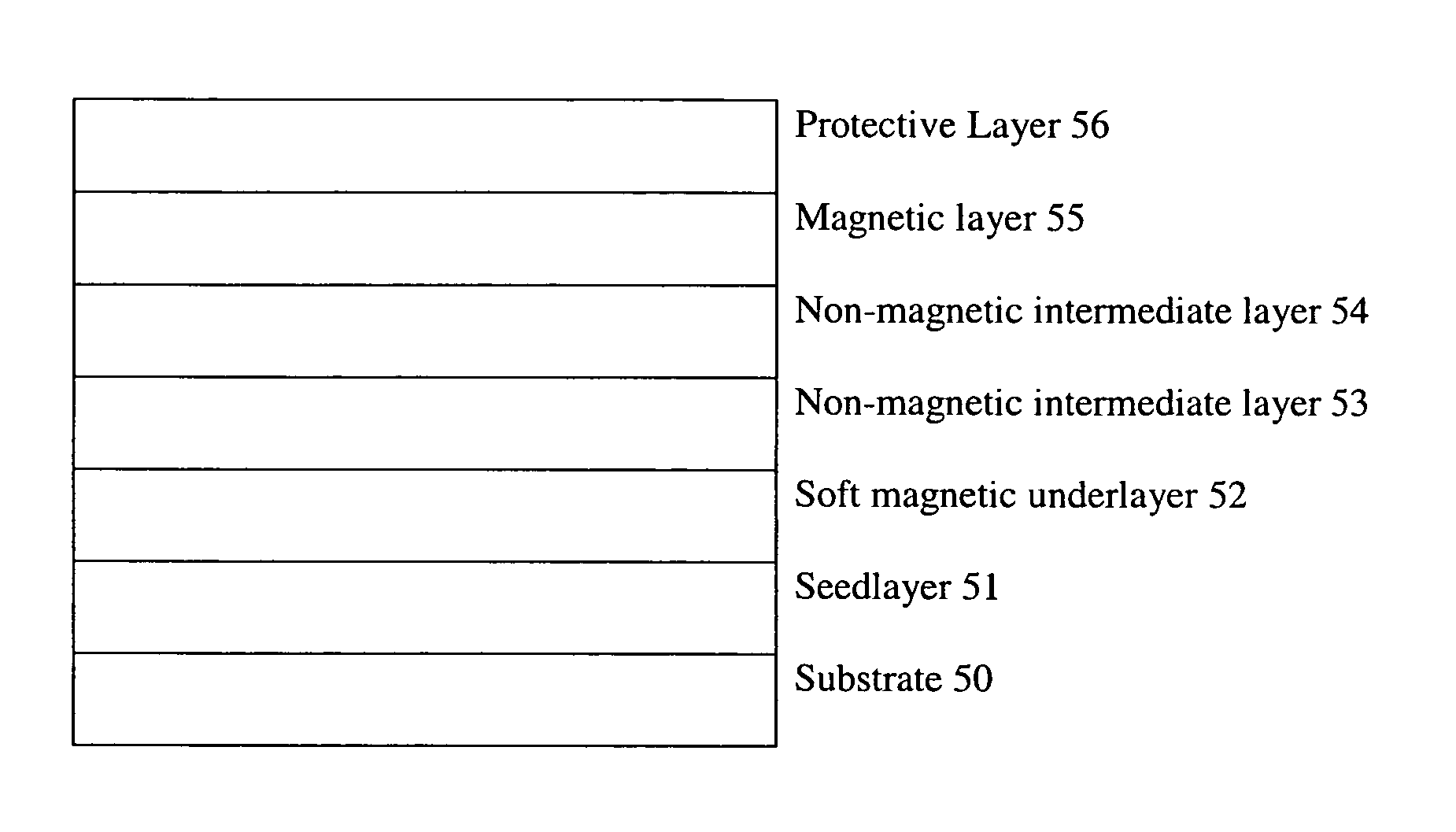
[0026]The invention provides a perpendicular magnetic recording medium having high areal recording density exhibiting low noise. One way of achieving this goal is to produce a soft magnetic film in the perpendicular magnetic recording medium with an easy axis substantially directed in a transverse direction to a traveling direction of a read-write head.

Problems solved by technology

It is extremely difficult to produce a magnetic recording medium satisfying such demanding requirements.
Medium noise in thin films is a dominant factor restricting increased recording density of high-density magnetic hard disk drives, and is attributed primarily to inhomogeneous grain size and intergranular exchange coupling.
The magnetization is most easily obtained along the easy axis of magnetization but most difficult along the hard axis of magnetization.
It is extremely difficult to produce a magnetic recording medium satisfying such demanding requirements, particularly a high-density magnetic rigid disk medium for longitudinal and perpendicular recording.
However, Barkhausen noise caused by domain wall motions in the soft underlayer can be a significant noise source.
However, both methods can cause complications in the disk manufacturing process.
The problem of making soft magnetic materials conventionally is that they usually have many crystalline boundaries and crystal grains oriented in many directions.
Applicants, however, have found that “all grains” oriented in the same direction would be very difficult to produce and would not be the “preferred soft material.” In fact, applicants have found that very high anisotropy is not desirable.

Method used


Image

  • Magnetic anisotropy of soft-underlayer induced by seedlayer
  • Magnetic anisotropy of soft-underlayer induced by seedlayer
  • Magnetic anisotropy of soft-underlayer induced by seedlayer

Examples


examples

[0065]All samples described in this disclosure were fabricated with DC magnetron sputtering except carbon films were made with AC magnetron sputtering.

example i

[0066]A single-disk type of sputtering machine with multi-vacuum chambers was used for fabricating NiFe alloy underlayers as shown in FIG. 4a. The diameter of magnetron source and disk were 7 inch and 84 mm, respectively. The CoCr40 seedlayers with 4–8 nm thickness were deposited on either heated or unheated disk substrates prior to deposition of NiFe films. The NiFe films were sputtered in argon gas pressure of 3 to 6 mtorr using 1 to 4 kW DC power. A fixed magnetron source was co-centric with disks during sputtering. The hysteresis loops of a 200 nm thick NiFe40 film deposited on 8 nm thick CoCr seedlayer, measured in radial and circumferential direction using a DMS vector VSM, are shown in FIG. 6. A “DMS vector VSM” is Model 10 VSM provided by Digital Measurement Systems. It is called vector VSM because the direction of field can be changed arbitrary with respect to sample.

[0067]The particular NiFe film of the disk whose hysteresis loop is shown in FIG. 6 was sputtered on unheate...


PUM

PropertyMeasurementUnit
thicknessaaaaaaaaaa
thicknessaaaaaaaaaa
thicknessaaaaaaaaaa

Abstract

A perpendicular magnetic recording medium having a substrate, a seedlayer on the substrate and a magnetic underlayer on the seedlayer, the magnetic underlayer having an easy axis of magnetization substantially directed in a radial or transverse direction, and a process for manufacturing the perpendicular magnetic recording medium are disclosed.

Description

RELATED APPLICATIONS[0001]This is a continuation-in-part of application Ser. No. 09 / 873,314, filed Jun. 5, 2001, now U.S. Pat. No. 6,709,773 which in turn claims benefit from Provisional Application Ser. No. 60 / 230,004, filed Sep. 5, 2000, entitled “Uniaxial Anisotropy of Soft-Underlayer Induced by Seedlayer,” the entire disclosure of which is hereby incorporated herein by reference. This application is also related to the application entitled “Magnetic Anisotropy of Soft-Underlayer Induced by Magnetron Field,” application Ser. No. 09 / 873,263, filed Jun. 5, 2001, the entire disclosure of which is hereby incorporated herein by reference.FIELD OF INVENTION[0002]This invention relates to perpendicular recording media, such as thin film magnetic recording disks having perpendicular recording, and to a method of manufacturing the media. The invention has particular applicability to high areal density magnetic recording media exhibiting low noise.BACKGROUND[0003]The increasing demands for...

Claims


Application Information

Patent Timeline
Patent Type & Authority Patents(United States)
IPC IPC(8): G11B5/66G11B5/70C23C14/02C23C14/16G11B5/73G11B5/852
CPCC23C14/025C23C14/165G11B5/667G11B5/852G11B5/732Y10T428/265G11B5/851G11B5/7379
Inventor CHANG, CHUNG-HEERANJAN, RAJIV Y.
Owner SEAGATE TECH LLC
Why Eureka
Try Eureka