Method and wireless communication hub for data communications

a data communication and wireless communication technology, applied in the field of wireless broadband communications, can solve the problems of preventing clients from generating and distributing substantial amounts of information into the network, the most expensive aspect of any broadband communication network is the cost of running cable from a service provider to each client, and the cost of installing fibre optic cables is estimated to cost tens of thousands of dollars per mile of installed cables. , the effect of reducing the attenuation of rain and other obstacles

Inactive Publication Date: 2007-03-20
HER MAJESTY THE QUEEN & RIGHT OF CANADA REPRESENTED BY THE MIN OF IND
View PDF12 Cites 15 Cited by
  • Summary
  • Abstract
  • Description
  • Claims
  • Application Information

AI Technical Summary

Benefits of technology

[0064]There are significant advantages to wireless systems operating at lower than 28 GHz frequencies and preferably in the range of 2–7 GHz. First, the electronics for driving the system is less costly since semiconductor devices operating at lower frequencies are currently cheaper and plentiful. Second, the attenuation due to rain and other obstacles is reduced Third, the antennas are physically smaller and are easily designed having high directivity and low sidelobe levels.

Problems solved by technology

Such asymmetry in communications prevents clients from both generating and distributing substantial amounts of information into the network.
As a consequence, the distribution of high content information by the network is exceedingly hierarchical, requiring the producers of information to access the hub nodes wherefrom the information is transmitted to the clients.
It is well known that one of the most expensive aspects of any broadband communication network is the cost of running cable from a service provider to each client.
For example, fibre optic cables are estimated to cost tens of thousands of dollars per mile of installed cable This results from labour costs, costs of routing the cables and obtaining rights to bury the cables, costs of repairing damaged cables and so forth.
Additionally, adding the capability to existing wireline infrastructure is expensive and problematic, often requiring the special conditioning of old lines or the addition of new infrastructure.
In many areas, infrastructure is simply not in place, forcing those desiring broadband communications to face the daunting task of not only installing links to clients, but also installing totally new switching systems.
Conventional broadband data distribution services are not capable of supporting such requirements.
Such a connection has many known problems.
The bandwidth is limited by the cable itself and division of subscribers into groups requires the addition of new hardware.
The bandwidth to any given client is limited by the number of active subscribers in their group and by the physical limitations on the information carrying capacity of the coaxial cable.
Further, such a system is highly asymmetric and incapable of, for example, supporting extensive video interactivity between client subscribers.
Some of the drawbacks of these systems are that they require the twisted pair telephone lines to be in good condition in order that the modems can be effectively used.
Also, networks employing ADSL are highly asymmetrical, having forward link capacity significantly larger than return link capacity.
In addition, unless the ADSL links are in good condition and relatively short, supporting high quality video services becomes problematic.
Another significant problem faced with ADSL is the requirement for a public telephone subscriber line network to be in place in order to facilitate deployment.
Such a requirement for an in-place infrastructure is simply impossible in many regions of the world, hence deployment of ADSL is limited to those regions that are well developed economically and have a solid technological base.
Despite the promise of LMDS there are a number of issues that compromise its acceptance as a widely deployed and ubiquitous wireless multimedia distribution system.
One significant drawback to the deployment of LMDS systems is the large signal attenuation that is faced by the frequencies used in transporting the data between the hub and subscriber terminals.
The underlying phenomena are well understood but are of such severity that current deployments of LMDS are limited to situations where the links are free from obstructions and where attenuation by rain or snow is sufficiently countered.
Another issue, also related to propagation characteristics, is that the intended polarization reuse schemes for increasing the capacity of LMDS systems are also prone to degradation by the same phenomena that attenuate the signal.
As a consequence there are issues of deployment and capacity, which bring into question the economic viability of LMDS systems.
Though there is much promise in LMDS systems operating at 28 GHz, the effect of the propagation environment makes wide scale deployment problematic.
The difficulty with using bands at lower frequencies is that there is insufficient bandwidth to support the density of communications demanded by broadband digital services and what bandwidth is available is often shared with other users such as satellite systems or dedicated point to point communications links.
At present, such a solution is unavailable for use with the types of data throughput anticipated and currently required.
Though it has been proposed that by using horizontal and vertical polarized sectors within a cell, LMDS providers can re-use bandwidth and multiply the number of T1 equivalents available, insufficient polarisation isolation makes such claims dubious especially in applications wherein subscribers are individuals and not businesses.
Unfortunately, LMDS has many known drawbacks and even though an LMDS television system was installed in Brooklyn in the early 1990's, it has failed to find wider acceptance.

Method used


Image

  • Method and wireless communication hub for data communications
  • Method and wireless communication hub for data communications
  • Method and wireless communication hub for data communications

Examples


examples

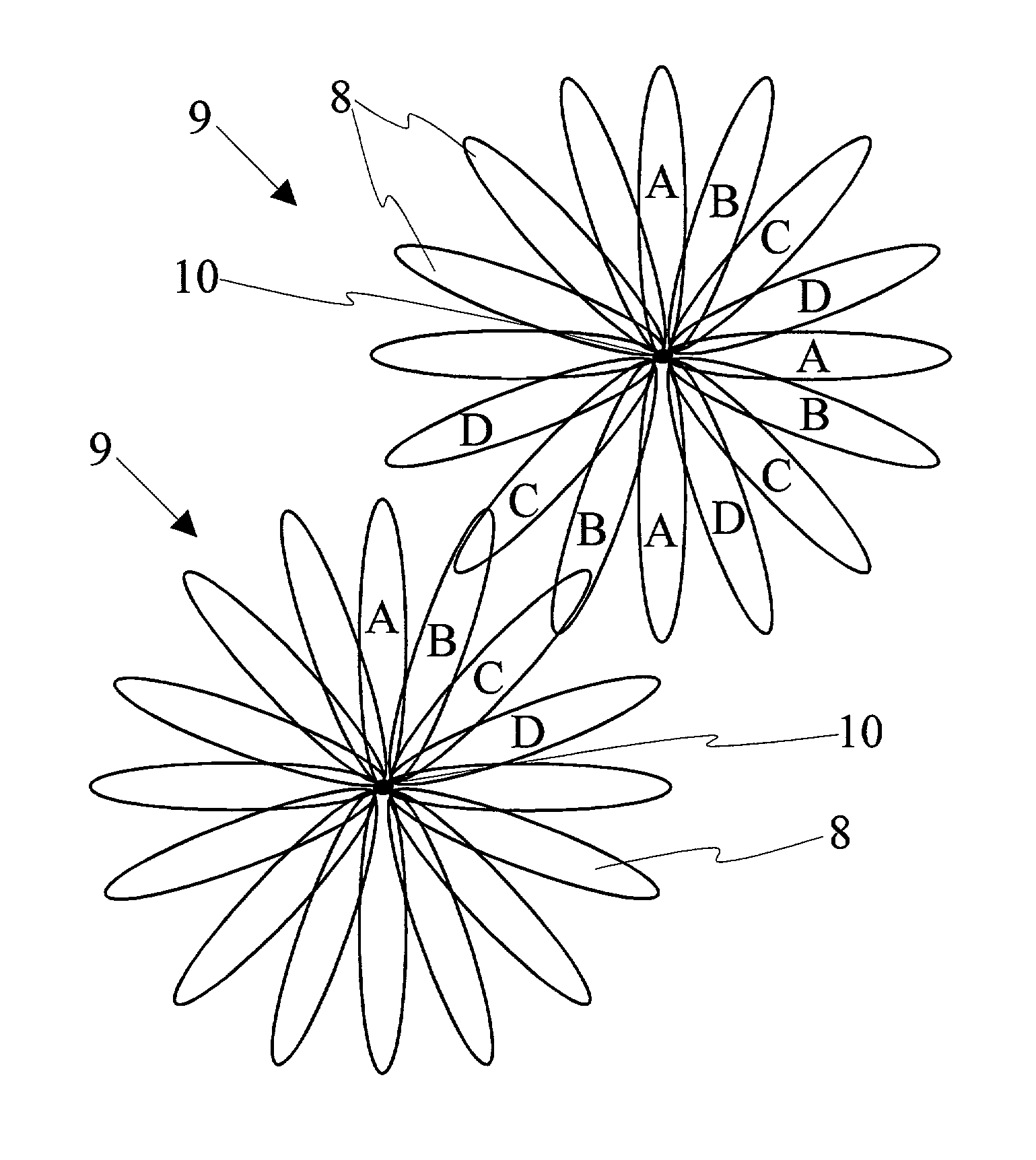
[0139]The Unlicensed National Information Infrastructure Frequency Allocations from 5.15 GHz to 5.825 GHz were used in a series of experiments conducted in an urban residential and commercial environment characterized by high foliage and roof top / building presence in the signal path. Tests were conducted with rosette petals having 11.25 degrees beamwidths in azimuth and elevation. Furthermore, simulation studies were conducted to examine the behaviour of constellations of rosettes over a contiguous coverage area. The simulations, where possible, used data taken from the experiments.

[0140]In both the experiments and simulation studies, frequencies were reused every 45 degrees thus requiring four different frequency ranges each reused 8 times. A parabolic Tx / Rx low sidelobe antenna having −30 dB sidelobes and a gain of 25 dBiC was used at the hub with subscriber antennas having similar characteristics. 200 MHz of spectrum was assigned to the system for the transmit (forward link) dire...


PUM


Abstract

The Highly Structured Rosette Antenna Array Data Communications System is a high capacity wireless network in which data is communicated from and to remotely located subscribers. The system uses cells that are comprised of a multiplicity of oblong microcells arranged in a circle, giving the cell a rosette-like pattern like frequency channels are assigned to every N′″ microcell, where N is the number of distinctly different frequency channels. The sum of the distinctly different channels is the total bandwidth assigned to the rosette. Typically, if M is equal to the total number of microcells in the rosette, then M/N is equal to the number of like-frequency microcells in the rosette.

Description

FIELD OF THE INVENTION[0001]The present invention relates to broadband communication networks and more particularly to wireless broadband communications.BACKGROUND OF THE INVENTION[0002]In the past, broadband communication was achieved by providing high bandwidth cable connections between a provider and a client. The cables are commonly in the form of coaxial cables, twisted pair copper telephone lines, or fibre optic cables. A broadband signal is transmitted down the cable toward the client end. For example, cable television involves a same signal transmitted to each client within a group of clients. The signals are sent in one direction only thus providing a one directional data link, Each client then decodes portions of the signal as desired.[0003]Information being sent to the clients, commonly called the down link or forward link, is usually transmitted at a much higher capacity than the up link or return link. Such asymmetry in communications prevents clients from both generati...

Claims


Application Information

Patent Timeline
Patent Type & Authority Patents(United States)
IPC IPC(8): H04Q7/20H04L12/28H04L12/56H04W16/24H04W84/00H04W84/14H04W88/00
CPCH04W84/14H04W84/00H04W16/24H04W88/00
Inventor SYDOR, JOHN T.
Owner HER MAJESTY THE QUEEN & RIGHT OF CANADA REPRESENTED BY THE MIN OF IND
Why Eureka
Try Eureka