Turbine exhaust water recovery system

a gas turbine engine and exhaust water technology, applied in the field of gas turbine engine exhaust water recovery system, can solve the problems of dissuading local decision-makers from building power plants, insufficient amount of freely available water to support plants, etc., and achieve the effect of reducing the effective duty of the absorption chiller and facilitating the movement of gas

Active Publication Date: 2007-03-27
AMEC FOSTER WHEELER IND POWER CO INC
View PDF23 Cites 80 Cited by
  • Summary
  • Abstract
  • Description
  • Claims
  • Application Information

AI Technical Summary

Benefits of technology

[0005]A first water recovery system according to aspects of the invention includes an absorption chiller. In one embodiment, the absorption chiller can be primarily powered by the heat energy of the exhaust gas in the exhaust duct. A supply conduit extends between and in fluid communication with the exhaust duct and the absorption chiller. The supply conduit receives a portion of the turbine exhaust gas and routes the gas to the absorption chiller. The absorption chiller reduces the temperature of the turbine exhaust gas to less than the dew point of the gas. As a result, at least some of the water vapor in the turbine exhaust gas condenses. The system includes a separator operatively associated with the absorption chiller. The separator removes at least a portion of the condensed water from the exhaust gas.
[0006]The system can further include a discharge conduit that is in fluid communication with and extends from the absorption chiller. The discharge conduit can route the gas out of the absorption chiller. The discharge conduit is in fluid communication with the exhaust duct. Thus, the gas can be returned to the exhaust duct. In one embodiment, a blower can be provided along the discharge conduit to facilitate the movement of the gas along the discharge conduit.
[0007]The system can further include a heat exchanger. The supply conduit and the discharge conduit can pass in heat exchanging relation through the heat exchanger such that the temperature of the gas in the supply conduit is reduced below the first temperature prior to entering the absorption chiller. Thus, the effective duty of the absorption chiller can be reduced.
[0010]The system can include a return conduit, which can be in fluid communication with the sump as well as the one or more water dispensing devices. The return conduit can route water from the sump to the one or more water dispensing devices for introduction to the turbine exhaust gas in the direct contact heat exchanger. A pump can be provided along the return conduit to facilitate the flow of water through the return conduit. A heat exchanger can be provided along the return conduit for reducing the temperature of the water to no more than about the ambient dry bulb temperature. The heat exchanger can be, for example, a fin-fan cooler.
[0014]The system also includes a first and second heat exchanger. The first heat exchanger is provided along the supply conduit upstream of the separator. The supply conduit and the discharge conduit pass in heat exchanging relation through the first heat exchanger. Thus, the first heat exchanger reduces the temperature of the exhaust gas in the supply conduit below the first temperature. The second heat exchanger, which can be a fin-fan cooler, is provided along the supply conduit downstream of the first heat exchanger and upstream of the separator. The second heat exchanger further reduces the temperature of the turbine exhaust gas to a temperature below the dew point of the gas. Thus, at least some of the water vapor in the turbine exhaust gas can condense, and the separator can removes at least a portion of the condensed water from the gas.

Problems solved by technology

For power plants located in such areas, there may be an insufficient amount of freely available water to support plant needs.
However, the lack of available water in some areas has dissuaded local decision-makers from building power plants.

Method used


Image

  • Turbine exhaust water recovery system
  • Turbine exhaust water recovery system
  • Turbine exhaust water recovery system

Examples


Embodiment Construction

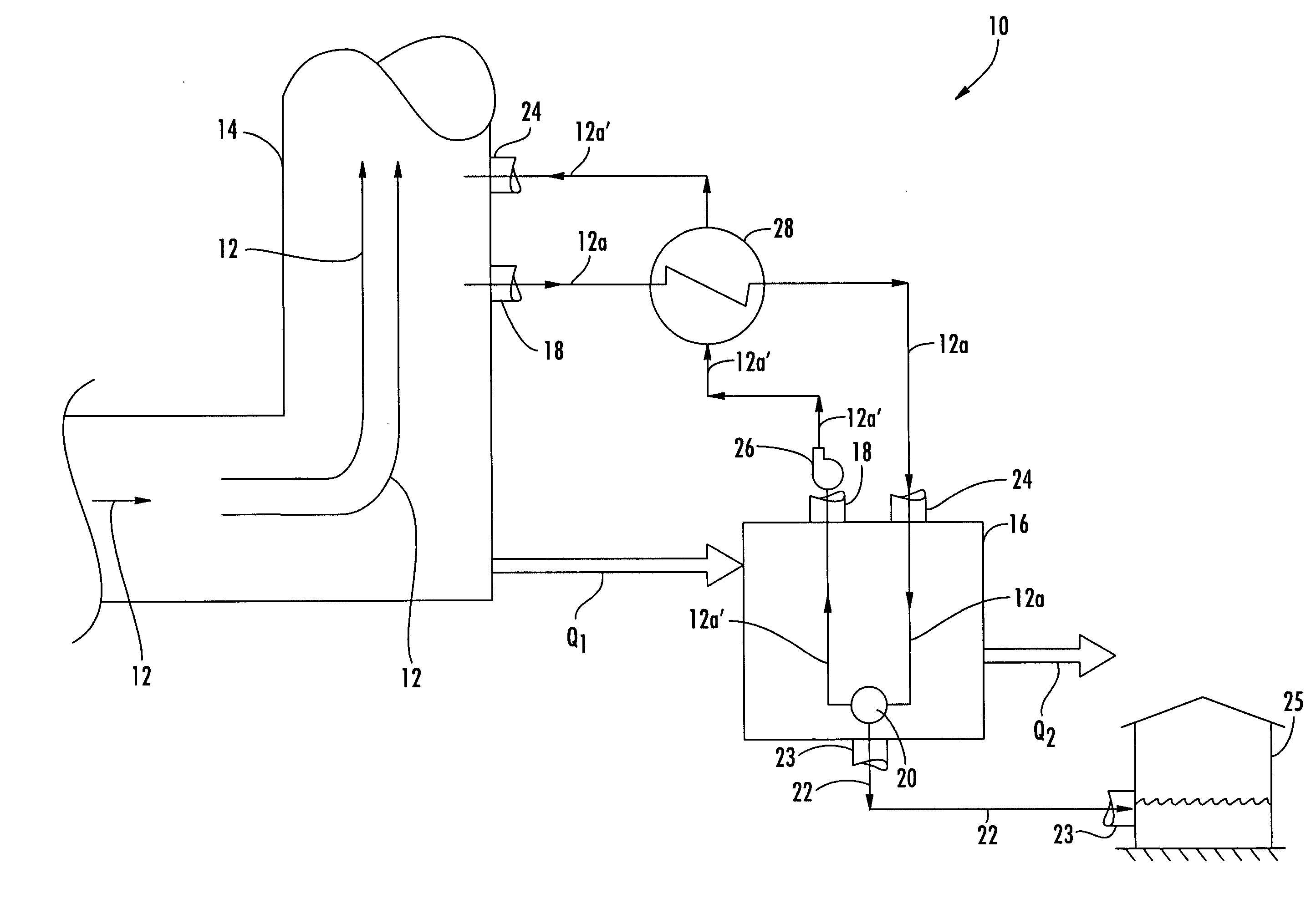
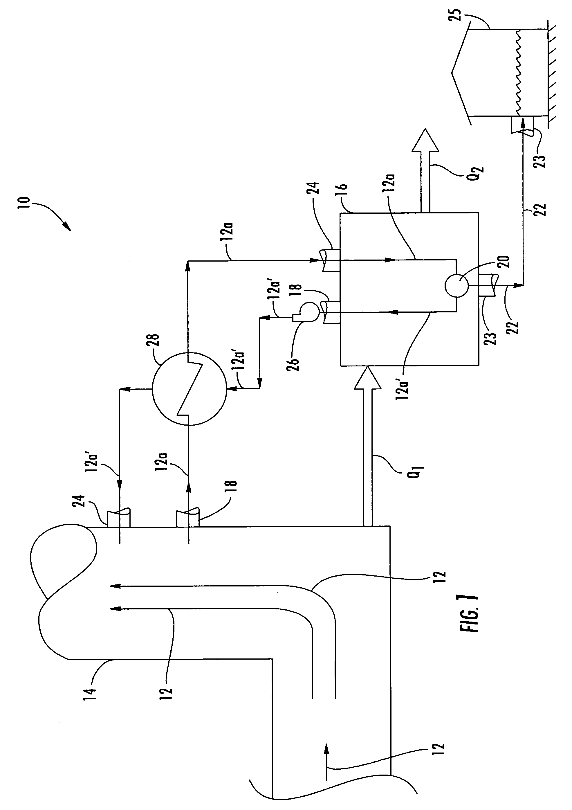
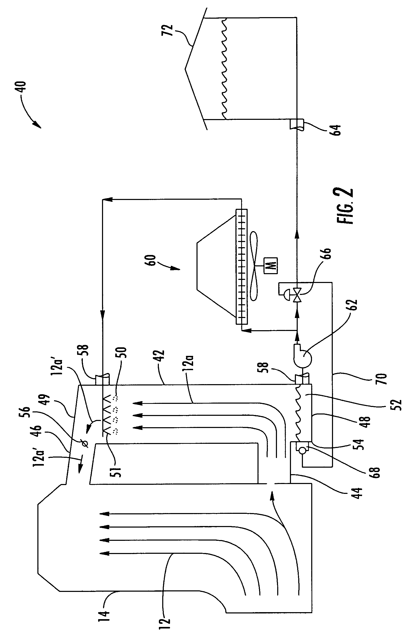
[0019]Embodiments of the invention present systems for extracting water from turbine exhaust gases. Embodiments of the invention will be explained in the context of various possible systems, but the detailed description is intended only as exemplary. Embodiments of the invention are shown in FIGS. 1–3, but the present invention is not limited to the illustrated structure or application.

[0020]In a gas turbine engine, fuel and air can be mixed and combusted to produce high pressure, high velocity gas. The gas can be routed to the turbine section of the engine where energy can be extracted from the gas. After exiting the turbine, the gas can be discharged to the environment through an exhaust stack or other exhaust duct. When a hydrocarbon-based fuel, such as natural gas, is used in the combustion process, one constituent of the combustion gas is water vapor. In one engine system, water vapor can be about five percent of the turbine exhaust mass flow. According to aspects of the invent...


PUM

PropertyMeasurementUnit
temperatureaaaaaaaaaa

Abstract

The exhaust gas of a turbine engine can include water vapor. Aspects of the invention relate to various systems for recovering water from the exhaust gas of a gas turbine engine. In one system, a portion of the exhaust gas can be routed to an absorption chiller. In another system, a portion of the exhaust gas can be routed to a direct contact heat exchanger. In a third system, a portion of the exhaust gas can be routed to a fin-fan cooler. In each of these systems, the portion of gas can be cooled below its dew point temperature to release a portion of its humidity as liquid water. Aspects of the invention can be used with the turbine exhaust of simple and combined cycle power plants. A water recovery system according to aspects of the invention can minimize or eliminate a power plant's dependence on local water sources.

Description

FIELD OF THE INVENTION[0001]The invention relates in general to gas turbine engines and, more particularly, to the exhaust of a gas turbine engine.BACKGROUND OF THE INVENTION[0002]Water is a scarce resource in certain areas of the world. For power plants located in such areas, there may be an insufficient amount of freely available water to support plant needs. Consequently, power plants have obtained water from other sources, such as rivers or wells. Some power plants have resorted to extracting and desalinizing ocean or brackish water. However, the lack of available water in some areas has dissuaded local decision-makers from building power plants.[0003]The dependence of a power plant on water can restrict the geographic possibilities for power plants to those areas where water is locally available, a permit can be obtained, and / or there is a reduced possibility of intervention from environmental interests. Thus, there is a need for system that can minimize these restrictions and ...

Claims


Application Information

Patent Timeline
Patent Type & Authority Patents(United States)
IPC IPC(8): F25B27/00
CPCF01D25/32
Inventor MCQUIGGAN, GERARDMYERS, GERALD A.CHHABRA, NITINGAIO, GIUSEPPE
Owner AMEC FOSTER WHEELER IND POWER CO INC
Why Eureka
Try Eureka