Microcontroller for fetching and decoding a frequency control signal together with an operation code
- Summary
- Abstract
- Description
- Claims
- Application Information
AI Technical Summary
Benefits of technology
Problems solved by technology
Method used
Image

Examples
first embodiment
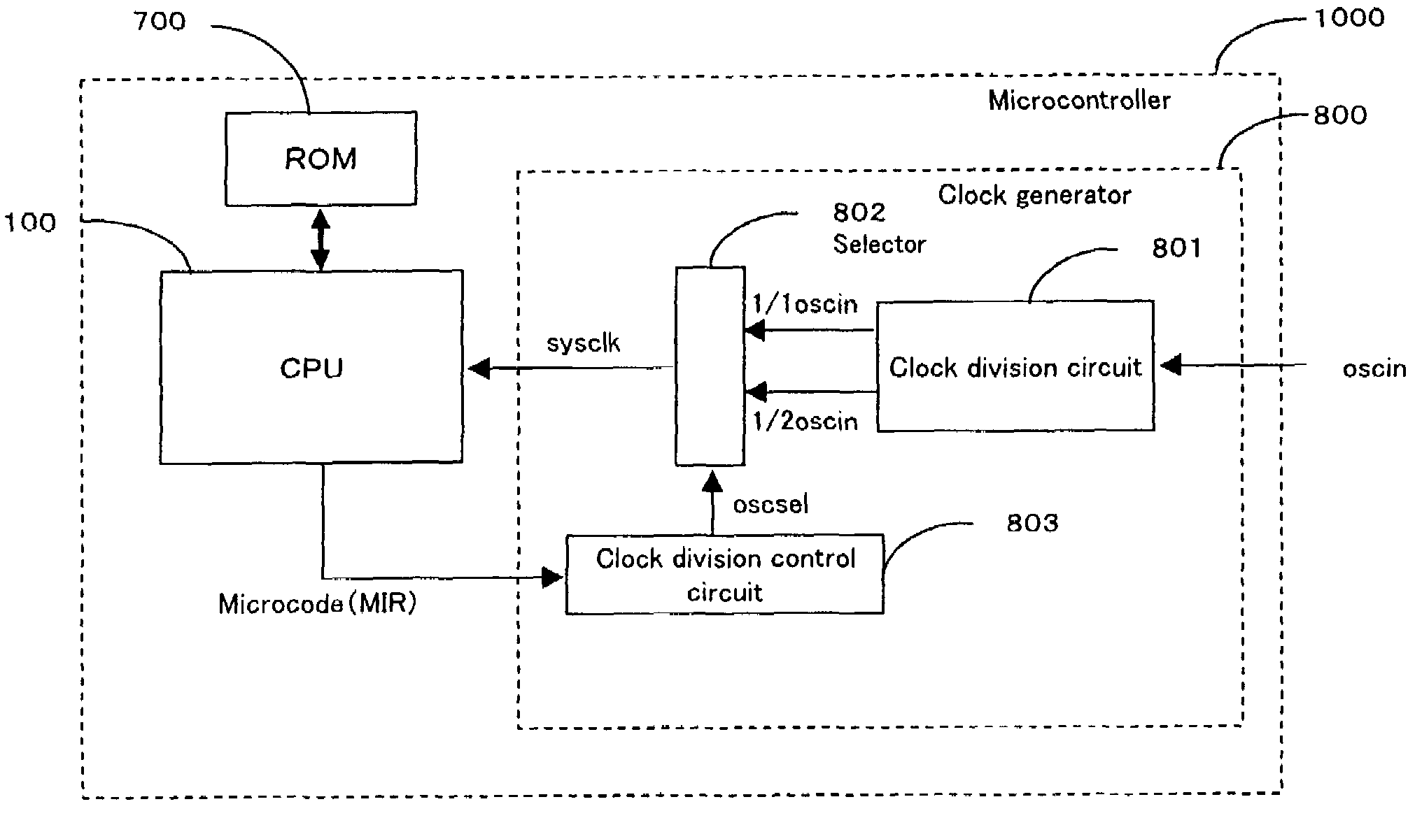
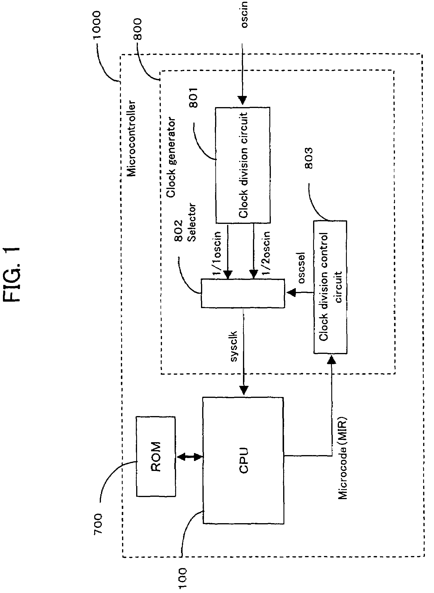
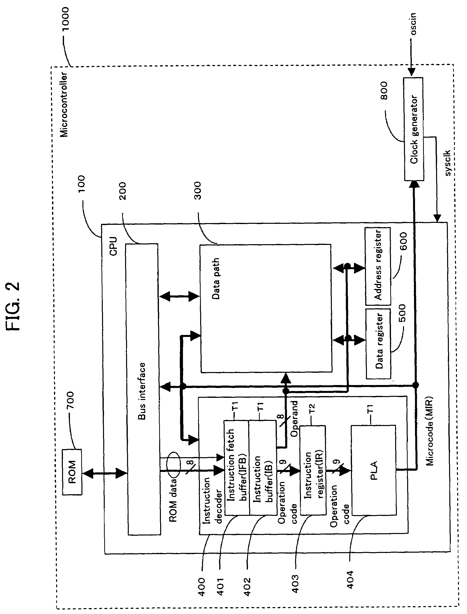
[0059]A microcontroller according to a first embodiment of the present invention will be described. FIGS. 1 and 2 are block diagrams showing the schematic structure of the microcontroller according to the first embodiment. FIG. 1 shows in detail the structure of a clock generator in the microcontroller. FIG. 2 shows in detail the structure of the CPU in the microcontroller.
[0060]In FIG. 1, reference numeral 1000 represents the microcontroller, and reference numeral 100 represents the CPU. The CPU 100 and a ROM 700 are connected together through a bus. A clock generator 800 with an original oscillation signal oscin as the input comprises a clock division circuit 801, a selector 802 and a clock division control circuit 803, and determines the division ratio of a system clock sysclk from a microcode MIR outputted from the CPU 100 and transmits it to the CPU 100. The microcontroller 1000 operates in synchronism with the system clock sysclk. The clock division circuit 801 divides the ori...
second embodiment
[0075]A microcontroller according to a second embodiment of the present invention will be described.
[0076]FIG. 4 is a block diagram showing the schematic structure of the microcontroller according to the second embodiment. In the second embodiment, the frequency control signal is not added to the operation code transmitted through the IFB 401, the IB 402, the IR 403 and the PLA 404 unlike in the first embodiment, and the operation code comprises 8 bits. Except this, the schematic structure is similar to that of the microcontroller of the first embodiment. Therefore, the internal structure of the clock generator 800 is the same as FIG. 1.
[0077]Next, the operation of the microcontroller according to the second embodiment structured as described above will be described.
[0078]FIGS. 5A and 5B show an example of the instruction map of the microcontroller of the second embodiment. The instruction map comprises a plurality of pages, and is classified into pages for each division ratio. Ther...
third embodiment
[0089]A microcontroller according to a third embodiment of the present invention will be described.
[0090]FIG. 7A is a flowchart showing the procedure of generating a machine code and disposing it into a ROM in the microcontroller according to the third embodiment. FIG. 7B is a view showing a method of generating the machine code from a program source by a compiler in the third embodiment. The circled numerals in FIG. 7B are replaced with (1) to (7) in the following description:
[0091]As shown in FIG. 7A, normally, the program source created by a program development is converted into a ROM code based on a data file generated by a complier or the like, and then, generated as a layout pattern and disposed into a ROM. However, according to conventional machine code generation flows, it is impossible to add the frequency control signal to the machine code like in the microcontroller of the first embodiment.
[0092]According to the machine code generation flow of the third embodiment, the fr...
PUM
 Abstract
Description
Claims
Application Information
 - R&D
- Intellectual Property
- Life Sciences
- Materials
- Tech Scout
- Unparalleled Data Quality
- Higher Quality Content
- 60% Fewer Hallucinations
Browse by: Latest US Patents, China's latest patents, Technical Efficacy Thesaurus, Application Domain, Technology Topic, Popular Technical Reports.
© 2025 PatSnap. All rights reserved.Legal|Privacy policy|Modern Slavery Act Transparency Statement|Sitemap|About US| Contact US: help@patsnap.com