Manufacture of thick preform composites via multiple pre-shaped fabric mat layers

a technology of fabric mats and composites, applied in the field of preform parts production, can solve the problems of large disadvantages of lom processes for fabricating composite structures, use only of thin-walled or shell-type composite structures, and inability to manufacture preform for thick composite parts, etc., and achieve the effect of increasing interlaminar connectivity

Inactive Publication Date: 2007-04-03
HONEYWELL INT INC +2
View PDF26 Cites 43 Cited by
  • Summary
  • Abstract
  • Description
  • Claims
  • Application Information

AI Technical Summary

Problems solved by technology

Current commercial P4 systems have the major disadvantage that they can be used only to manufacture thin-walled or shell-type composite structures—they cannot be used to make preform for thick composite parts.
LOM processes have major disadvantages for fabricating composite structures.
This cutting process is inefficient in its use of material, and a large quantity of scrap material is produced.
This scrap rate becomes unacceptable if material costs are to be reduced.
Building structures with internal cavities is limited, as additional cutting and lift-up processes have to be included in such cases.
The incorporation of gradients in material properties within the LOM is limited to a layering approach.
The planar build technique does not allow for interconnection between the individual layers beyond the adhesive used to bond the individual layers.
Finally, the LOM process is limited to the assembly of initially flat sheets of material.
The planar build technique does not allow for interconnection between the individual layers beyond the adhesive use to bond the individual layers.
Moreover, the lack of necessity for extensive cutting facilitates the manufacture of preforms for composite parts having internal cavities.

Method used


Image

  • Manufacture of thick preform composites via multiple pre-shaped fabric mat layers
  • Manufacture of thick preform composites via multiple pre-shaped fabric mat layers
  • Manufacture of thick preform composites via multiple pre-shaped fabric mat layers

Examples


Embodiment Construction

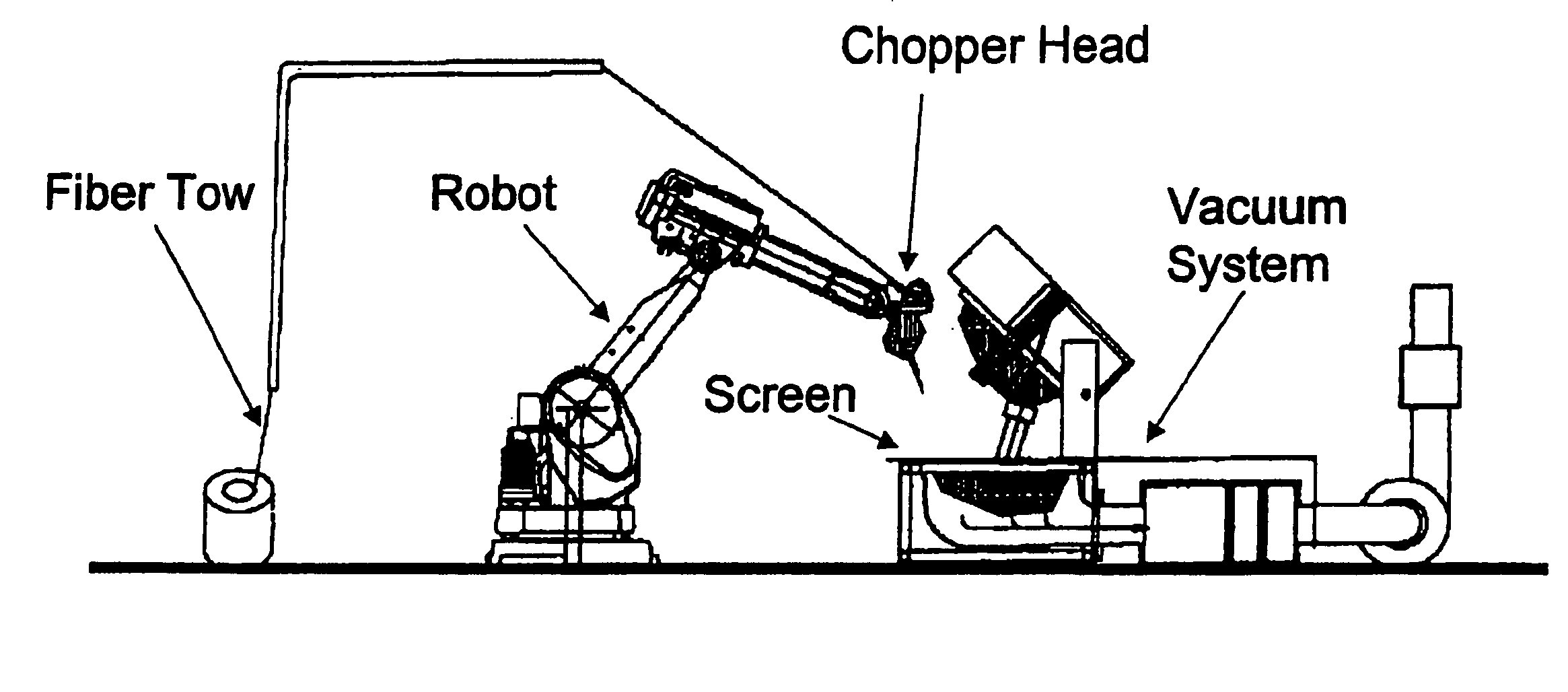
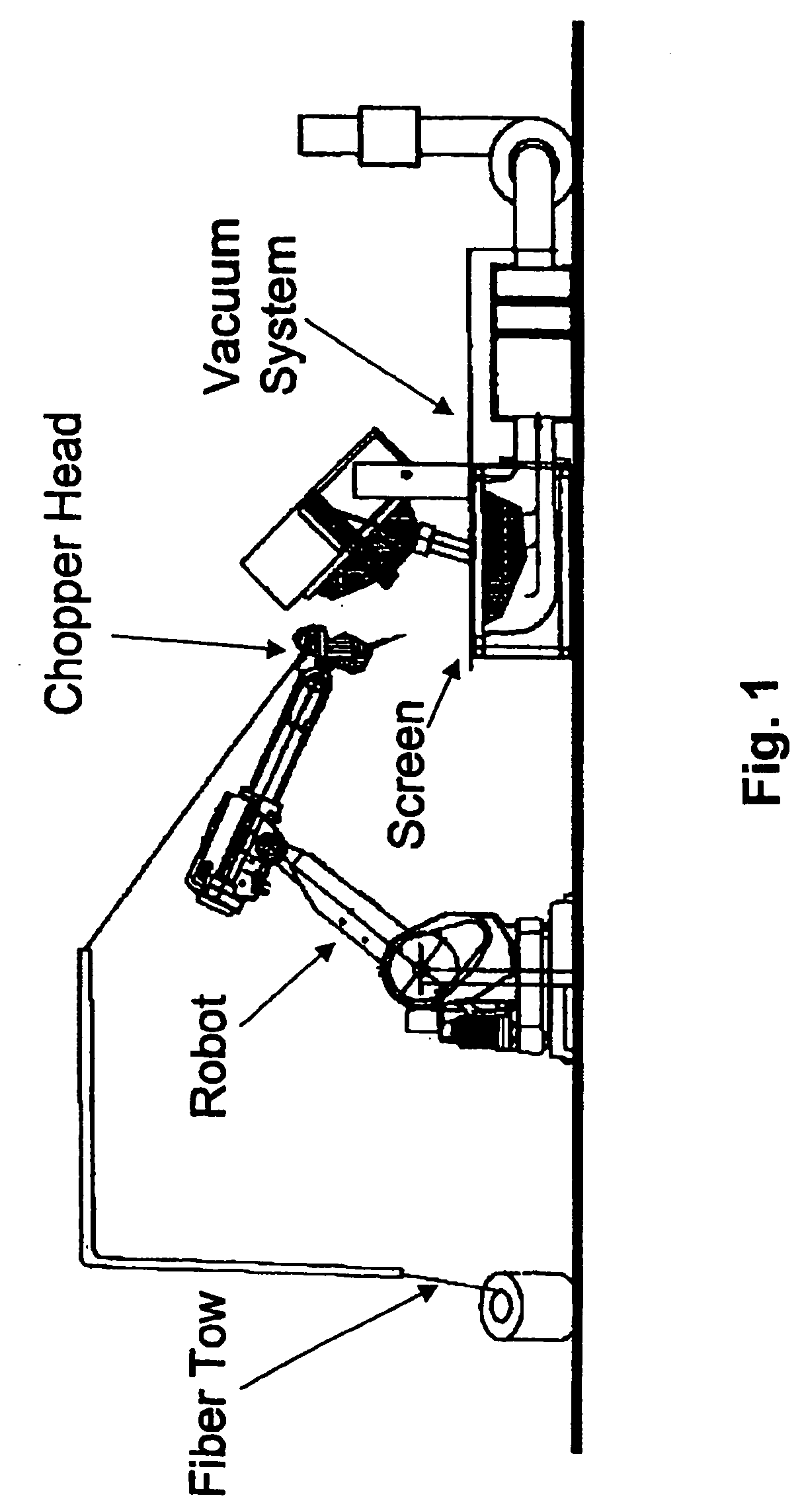
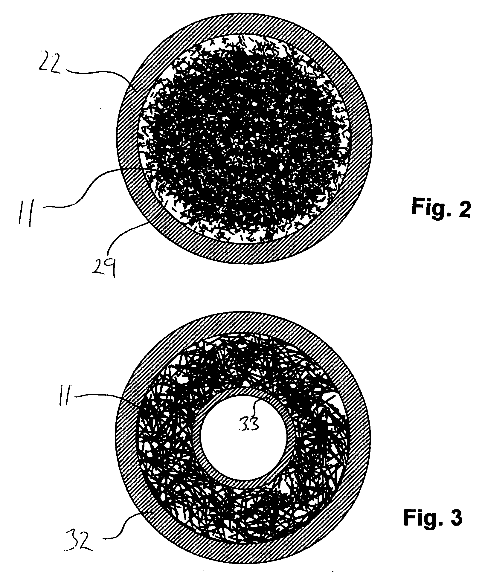
[0024]This invention provides a process for the manufacture of preforms for thick structural composite parts. In accordance with this invention, individual layers of fiber mats with defined microstructure are produced by means of a fiber spray system. The individual fiber mats are subsequently stacked to make a multi-layer composite preform. The individual fiber mats are interlinked, for example by needling of the three-dimensional preform or by the use of tabs and lugs built into the individual fiber mats or by virtue of three-dimensionality in the individual fiber mats themselves. The fiber preform is densified by resin infiltration. The novel manufacturing apparatus, comprising one or more fiber spray-up and layer assembly stations, also constitutes an aspect of this invention.

[0025]The present inventive system for the fabrication of preforms for thick, three-dimensional composite parts includes various components. One component of this invention is a robotic process for chopping...


PUM

PropertyMeasurementUnit
thicknessaaaaaaaaaa
densityaaaaaaaaaa
thicknessaaaaaaaaaa

Abstract

Preform for carbon-carbon composite part (55) comprising multiple layers of fibrous mats (51, 52, 53) wherein each mat (51, 52, 53) comprises random carbon-containing fibrous matrix (11) having polymeric binder distributed therein and wherein adjacent mats (51, 52, 53) are bound together by additional polymer binder, stitching, and interlocking tabs. Also, method of manufacturing thick multi-layer composite preform, by: providing optionally reconfigurable tool including perforated screen through which vacuum can be drawn; delivering chopped fibers (b) to the tool while drawing vacuum therethrough to form fibrous object; delivering binder (c) to the fibrous object; melting or curing the binder (d) to make a fibrous mat (51, 52, 53); assembling plurality of the fibrous mats (51, 52, 53) and additional binder into the shape of a preform (e); and heat-pressing the resulting mat assembly (f) into finished thick preform (55).

Description

BACKGROUND[0001]The present invention relates to a method of producing preform parts by layering fibrous objects. The fibrous objects that are layered in this invention are nonwoven fiber mats produced, by a spray deposition process. The present invention is particularly well adapted for the use of near-net shape fiber mats, that is, mats whose relevant dimensions are quite close to the corresponding dimensions of the final product being manufactured. This significantly reduces the amount of cutting processes and corresponding material waste in the manufacture of the desired preforms and the final composite parts made from these preforms. The present invention is particularly advantageous in the manufacture of carbon-carbon brake discs due to the high raw material and processing cost for this type of material.[0002]Composite materials are materials of choice in many industrial applications, including the application of carbon-carbon composites to brake components. In these carbon-ca...

Claims


Application Information

Patent Timeline
Patent Type & Authority Patents(United States)
IPC IPC(8): B29C70/12B29C70/34B32B3/02B29B11/16B29C70/30B29C70/38D04H1/00D04H13/00F16D69/02
CPCB29B11/16B29C70/305D04H1/005F16D69/023B29L2031/7482Y10T428/213D04H13/006F16D2069/008D04H13/002D04H1/593D04H1/60D04H1/76
Inventor LA FOREST, MARK L.GHARBIEH, NABIL ABUCIPRA, RAYMOND J.FATZ, ALAN E.SIEGMUND, THOMAS H.
Owner HONEYWELL INT INC
Why Eureka
Try Eureka