Pressure contact holding-type connector

a technology of holding type and connector, which is applied in the direction of coupling contact member, coupling device connection, electrical apparatus, etc., can solve the problem of not-significant risk of degrading assemblability, and achieve the effect of reducing the load required for pushing, eliminating the risk of connector, and stable connection

Inactive Publication Date: 2007-04-10
SHIN-ETSU POLYMER CO LTD
View PDF19 Cites 31 Cited by
  • Summary
  • Abstract
  • Description
  • Claims
  • Application Information

AI Technical Summary

Benefits of technology

[0011]The present invention further improves the pressure contact holding-type connector shown in FIG. 12, and it is an object thereof to provide a pressure contact holding-type connector in which deformation of the spring element and separation of the plug from the spring element, and damage of the plug, are prevented.
[0014]The present invention eliminates a risk of the connector, in particular the coil spring, being damaged or deformed. Furthermore, a load required for pushing can be decreased, stable connection can be provided, damage to electrodes that are connected can be significantly reduced, and further miniaturization of the connector is attained.

Problems solved by technology

In the connector for electric connection shown in FIG. 10, because a contact terminal is inserted into a board and fixed therein by soldering, there is a not-insignificant risk of degrading assemblability.

Method used


Image

  • Pressure contact holding-type connector
  • Pressure contact holding-type connector
  • Pressure contact holding-type connector

Examples


example

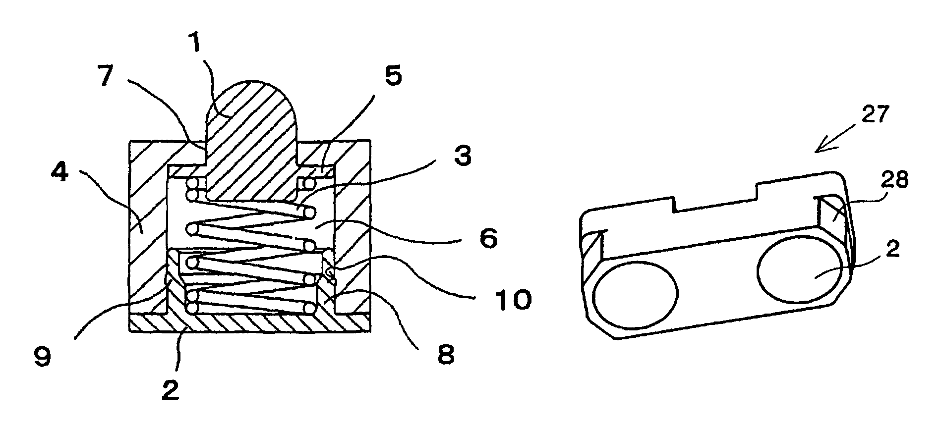
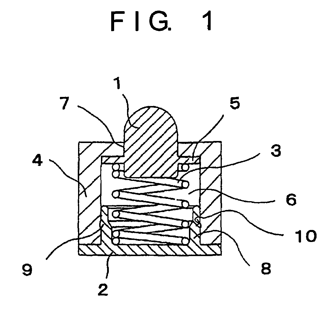
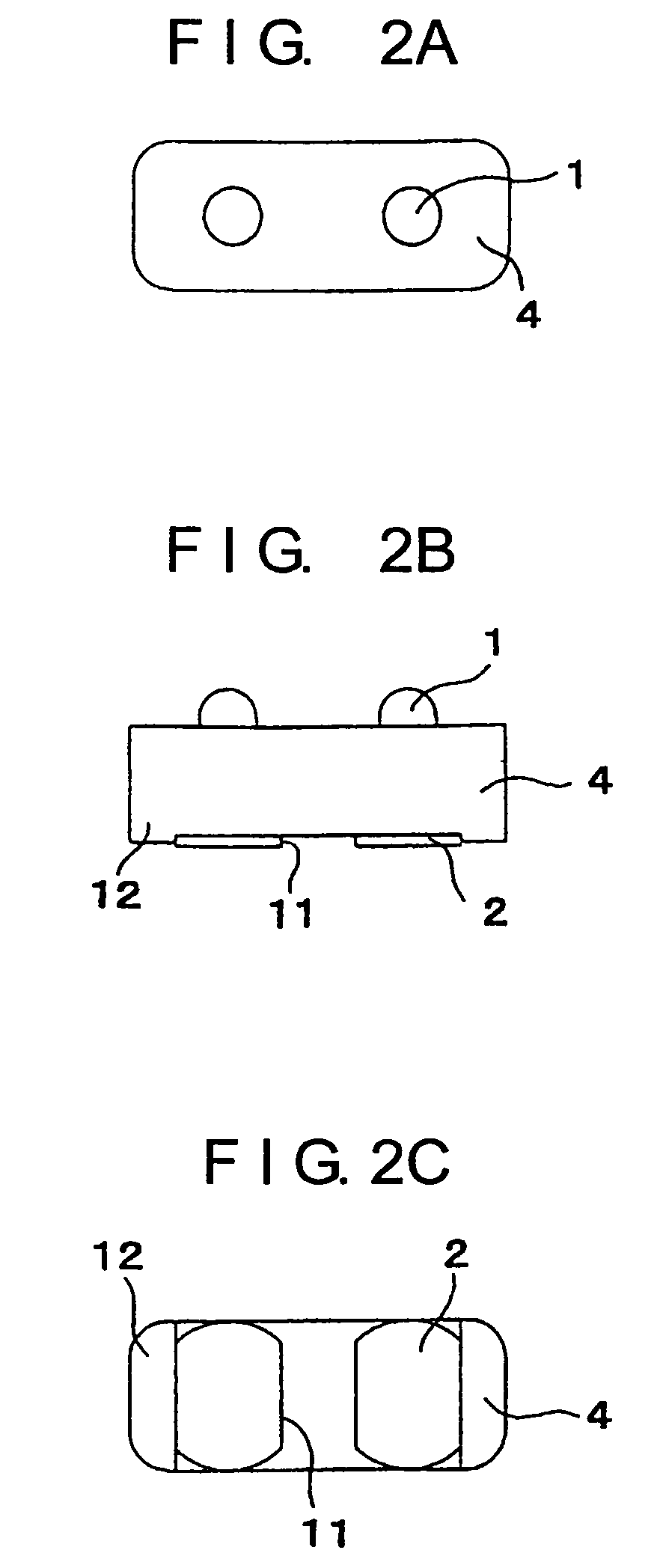
[0068]A fabrication example of the pressure contact holding-type connector in accordance with the present invention shown in FIG. 1 and FIGS. 2A–2C will be described below.

[0069]A housing having a length of 2 mm, width of 5 mm, and height of 2.1 mm was made from a polyamide resin. A conductive pin was fabricated from brass with gold plating. A coil spring was fabricated from a piano wire plated with a copper layer of a 4 μm thickness, then with a nickel layer of a 3 μm thickness and, as an outermost layer, with a gold layer of a 0.1 μm thickness, and had a wire diameter, pitch, and length (during assembling) of 0.1 mm, 0.4 mm, and 1.3 mm, respectively.

[0070]A stroke was 0.5 mm, a pushing load was 1 N per conductive pin, and electric resistance between connected electrodes was 0.2Ω per electrode pair.


PUM


Abstract

A pressure contact holding-type connector in accordance with the present invention is configured to be interposed between opposing electrodes. A conductive pin is located in at least one end portion of each through-hole of an insulating housing having a through-hole oriented in a thickness direction. A flange section provided on the conductive pin is mated with a small-diameter section provided in one end portion of the through-hole to maintain at least part of the conductive pin in a state of accommodation inside the through-hole. And, a conductive coil spring having one end thereof mated with the flange section provided on the conductive pin and pushing the conductive pin with a snap to an exterior of the through-hole is installed inside the through-hole. The conductive pin can be disposed at both ends of the coil spring.

Description

TECHNICAL FIELD[0001]The present invention relates to a pressure contact holding-type connector, and more particularly to a pressure contact holding-type connector in which a conductive pin of the connector does not slip out of a housing.BACKGROUND ART[0002]Connector pins for electric connection are known as structure for conductively connecting, via elastic contact, and providing signal transfer between electronic circuits on a pair of boards disposed opposite each other in a variety of electronic devices (see Japanese Patent Application Laid-open No. H7-161401). Furthermore, the inventor suggested pressure contact holding-type connectors with improved connector pins for electric connection (Japanese Patent Applications Laid-open No. 2002-100431, 2002-158052, and 2002-158053).[0003]A connector pin for electric connection (Japanese Patent Application Laid-open No. H7-161401) is described, as shown in FIG. 10, as a connector 46 for electric connection, comprising: a connector pin 43 ...

Claims


Application Information

Patent Timeline
Patent Type & Authority Patents(United States)
IPC IPC(8): H01R13/24
CPCH01R13/2421H01R13/24
Inventor SASAKI, YUICHIRO
Owner SHIN-ETSU POLYMER CO LTD
Why Eureka
Try Eureka