Induction heating method and unit

a technology of induction heating and heating coils, applied in the direction of induction current sources, electric/magnetic/electromagnetic heating, coil arrangements, etc., can solve the problems of inability to achieve uniform heating, difficult high-precision control of heating temperature, and so as to achieve precise temperature control, improve power factor, and avoid temperature decrease in the border portion of the heating coils

Inactive Publication Date: 2007-04-10
MITSUI E&S MACHINERY CO LTD
View PDF21 Cites 19 Cited by
  • Summary
  • Abstract
  • Description
  • Claims
  • Application Information

AI Technical Summary

Benefits of technology

[0025]In the induction heating method of the present invention as structured above, since the frequencies of the currents supplied to the plural heating coils are equalized and the phases are synchronized with each other or maintained at the phase difference to be set, the state of the mutual induction among the heating coils can be fixed without being influenced by the load fluctuation even when the load fluctuates. Therefore, no distortion of a waveform and so on occurs to the currents (heating coil currents) supplied to the respective heating coils due to the change in the mutual induction so that the inverters can operate normally, and even when the plurality of the heating coils are disposed adjacent to each other, the temperature can be easily and precisely controlled by the heating coils and the temperature decrease in the border portions of the heating coils can be prevented.
[0027]In the induction heating method of the present invention, the subordinate inverter is driven in such a manner that the drive signal for driving the main inverter is given to the subordinate inverter, and based on this, the phase of the current supplied to the heating coil on the subordinate inverter side is synchronized with the phase of the current supplied to the heating coil on the main inverter side or the phase difference to be set is maintained therebetween, and in addition, by controlling the reactor on the subordinate inverter side, the phases of the output current and the output voltage of the subordinate inverter are made to coincide with each other. Therefore, according to the present invention, the phases of the currents through the heating coils of the main inverter and the subordinate inverter can be synchronized or fixed, a precise temperature control without any influence by the load fluctuation is possible, and the temperature decrease in the border portion of the heating coils can be avoided. In the main inverter, the drive control section makes the frequency adjustment so as to have the phases of the output voltage and the output current coincide with each other, and in the subordinate inverter, the reactor is adjusted so as to have the phases of the output current and the output voltage coincide with each other, and therefore, a power factor can be improved and output efficiency of the inverters can be enhanced so that decrease in operation efficiency can be prevented.
[0028]Furthermore, the phase difference between the output current and the output voltage of the subordinate inverter is adjusted after the phase difference between the current supplied to the heating coil on the main side and the current supplied to the heating coil on the subordinate side is obtained and the adjustment is made to eliminate this phase difference between the currents.
[0029]Incidentally, the same effect can be obtained when the output frequency of the output current or the output voltage of the main inverter is given as the drive signal of the subordinate inverter instead of the drive signal for driving the main inverter and the subordinate inverter is operated being synchronized with the output frequency of the main inverter or maintaining the phase difference to be set. Further, by providing the output power control sections to respectively correspond to the main inverter and the subordinate inverter, the amount of the output of each of the inverters can be freely controlled and heating temperature can be controlled freely and highly precisely.

Problems solved by technology

Consequently, in the induction heating unit including the heating coils corresponding to the plural inverters, unless the frequencies of the respective load currents are equalized and the phases of the respective heating coil currents are fixedly maintained, a highly precise control of a heating temperature becomes difficult and the temperature decrease in the border portions of the heating coils is caused.
The method described above in which the magnetic force shielding coils are disposed in the border portions of the heating coils, however, cannot achieve uniform heating since the magnetic fluxes in the end portions of the coils are absorbed by the magnetic force shielding coils to cause the temperature decrease in these portions.
The method in which the variable reactor is connected in series to one of the heating coils to vary a voltage by the variable reactor as described in Japanese Utility Model Publication No. 3-39482 also has such disadvantages that controlling the variable reactor changes the entire frequency, a time constant of power control is long, the power control of one unit changes a power value of each of the heating coils of the entire system so that it is difficult to independently control temperature for each of the heating coils, and so on.
Meanwhile, in each of the inverters, inverter output efficiency (power factor) becomes low unless a phase difference between its output current and output voltage is made small so that capacity decrease and efficiency degradation of the inverter are caused.

Method used


Image

  • Induction heating method and unit
  • Induction heating method and unit
  • Induction heating method and unit

Examples


first embodiment

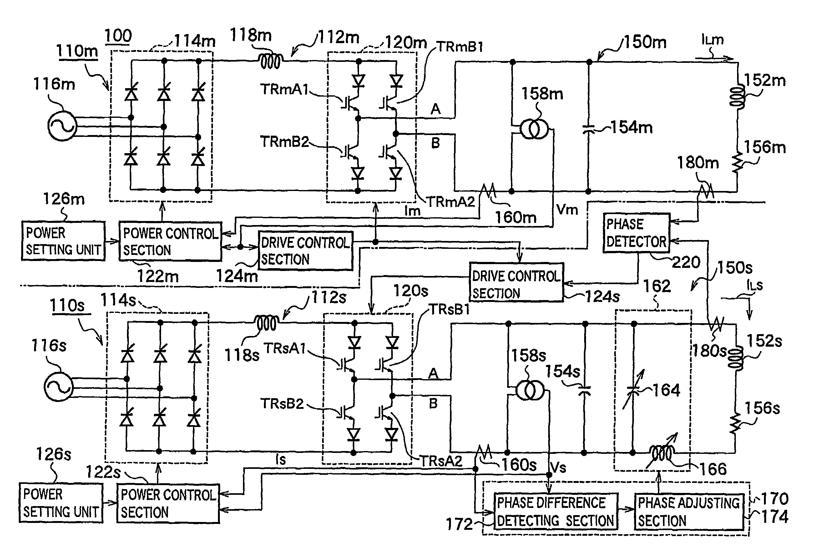
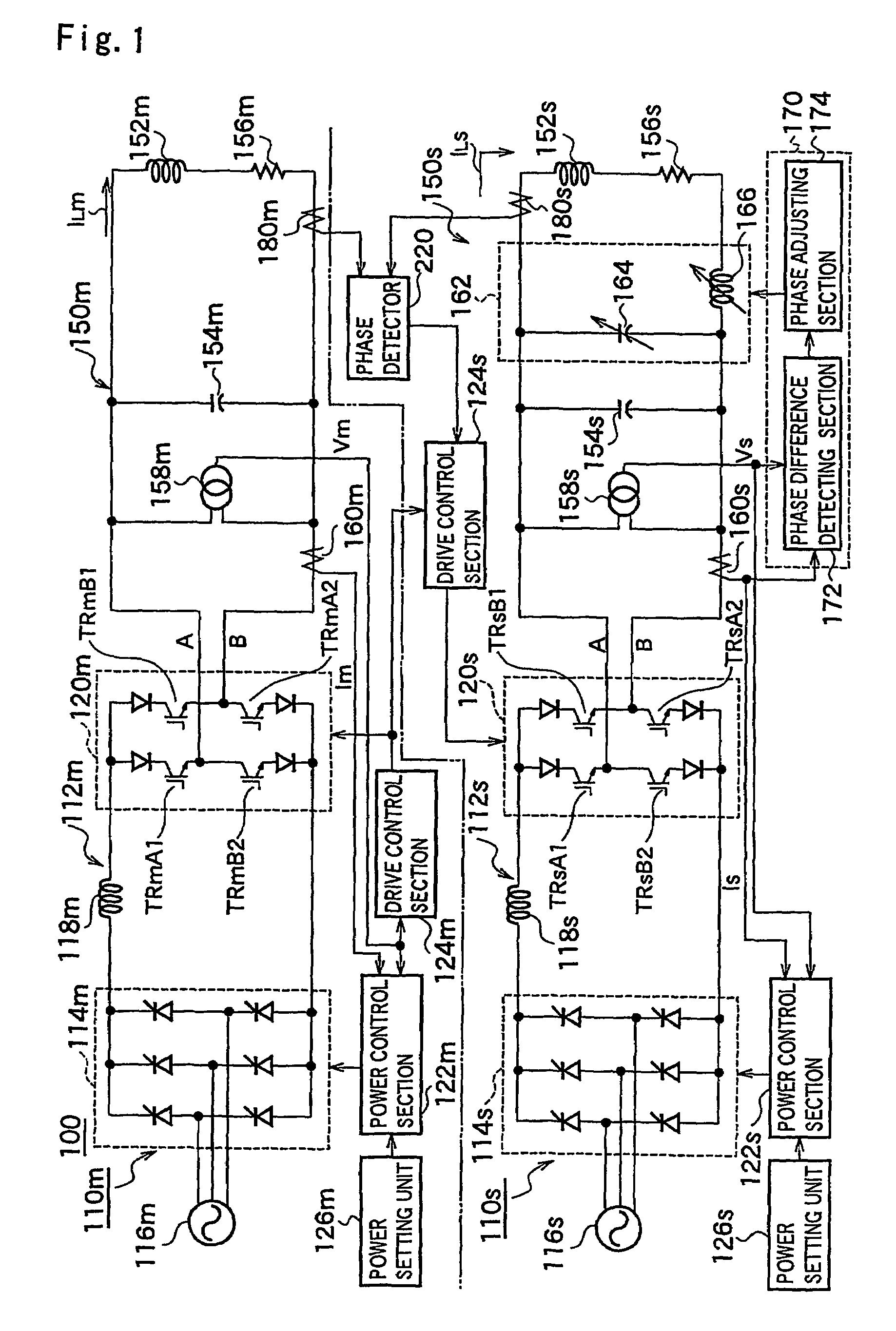
[0049]FIG. 1 is an explanatory view of an induction heating unit according to the present invention. An induction heating unit 100 according to this embodiment is composed of a pair of a main heating unit 110m and a subordinate heating unit 110s. The heating units 110m, 110s include power supply sections 112m, 112s and load coil sections 150m, 150s which are supplied with power from these power supply sections 112m, 112s, respectively.

[0050]The power supply sections 112m, 112s include forward converting sections 114m, 114s respectively, each being a rectifying circuit in which a bridge circuit is formed by thyristors, and these forward converting sections 114m, 114s are connected to three-phase AC power supplies 116m, 116s respectively. An inverter (inverse converting section) 120m and an inverter 120s are connected to output sides of the forward converting sections 114m, 114s via smoothing reactors 118m, 118s. In the embodiment, the inverter 120m on a main heating unit 110m side is...

second embodiment

[0072]In the second embodiment thus configured, the drive control section 212s on the subordinate side, when the voltage Vm on the main side is inputted thereto, detects a zero cross of the voltage Vm similarly to the drive control section 124m on the main side, generates a transistor gate pulse for A phase and a transistor gate pulse for B phase in synchronization with this zero cross, and gives them as drive signals to bases of respective transistors of the inverter 120s. Thereby, the same effect can be obtained as that in the above-described embodiment.

[0073]Incidentally, it is also suitable that a current Im outputted by a current transformer 160m on the main side is inputted to the drive control section 212s on the subordinate side, the transistor gate pulse is generated based on this current Im, this is given to the transistors of the inverter 120s on the subordinate side, and the inverter 120s on the subordinate side is operated in synchronization with the current Im on the m...

third embodiment

[0074]FIG. 14 is a diagrammatic explanatory view of a third embodiment, showing an example where the present invention is applied to a voltage-type inverter. In FIG. 14, an induction heating unit 300 is so configured that a forward converting section 304 is connected to an AC power supply 302 and a smoothing condenser 306 is provided on an output side of this forward converting section 304. Further, the induction heating unit 300 is so configured that a heating unit 310m on a main side and a heating unit 310s on a subordinate side are connected in parallel to the smoothing condenser 306.

[0075]The heating units 310m, 310s have DC power supply sections 312m, 312s, inverters 314m, 314s, and load coil sections 320m, 320s respectively. The DC power supply sections 312m, 312s are composed of generally known chopper circuits 316m, 316s and condensers 318m, 318s provided on output sides thereof. Each of arms of each of the inverters 314m, 314s is constituted by a bridge circuit which is com...


PUM


Abstract

It is an object of the present invention to prevent temperature decrease in a border portion of each of heating coils and to enable to eliminate an influence given by the change in a load state. In order to attain this object, an induction heating unit 400 according to the present invention is provided with control units 420 (420a to 420d) respectively corresponding to a plurality of heating units 310 (310a to 310d). A phase detector 424d of the control unit 420d obtains a phase difference between an output current (heating coil current IL4) of an inverter 314d detected by a current transformer 160d and a reference signal outputted by a reference signal generating section 426, and inputs it to a drive control section 422d. The drive control section 422d adjusts an output timing (phase) of a gate pulse to be given to the inverter 314d so as to make a phase of the heating coil current IL4 of the inverter 314d coincide with a phase of the reference signal outputted by the reference signal generating section 426. A phase control section 334d controls a variable reactor 326d so as to make the phases of an output voltage and the output current (heating coil current IL4) of the inverter 314d coincide with each other, and improves a power factor of the inverter 314d. Each of the other control units 420a to 420c also performs the same control operation.

Description

TECHNICAL FIELD[0001]The present invention relates to an induction heating method and unit, more particularly to an induction heating method and unit suitable for supplying electricity by resonance-type inverters provided to respectively correspond to plurality of heating coils which are disposed adjacent to each other.BACKGROUND ART[0002]Induction heating is to produce heat in such a manner that a magnetic field is generated by the passage of currents through heating coils to generate an overcurrent in a member to be heated, and it is adopted in various fields since it can generate a high temperature which cannot be obtained by resistance heating. FIG. 8 schematically shows the outline of an induction heating unit which hardens a roll of a rolling mill and so on.[0003]In FIG. 8, a roll 10 is composed of a roll body 12 and journals 14 disposed at both ends thereof. When the roll 10 is to be hardened by the induction heating, a heating coil 16 which generates a magnetic field with a ...

Claims


Application Information

Patent Timeline
Patent Type & Authority Patents(United States)
IPC IPC(8): H05B6/04A45D20/12H05B6/06H05B6/12H05B6/14H05B6/44
CPCA45D20/12H05B6/04H05B6/145H05B6/067H05B6/06H05B6/12
Inventor UCHIDA, NAOKIKAWANAKA, KEIJINANBA, HIDEYUKIOZAKI, KAZUHIRO
Owner MITSUI E&S MACHINERY CO LTD
Why Eureka
Try Eureka