Scintillator compositions of cerium halides, and related articles and processes

a technology of cerium halide and composition, which is applied in the direction of instruments, nuclear engineering, conversion screens, etc., can solve the problems of affecting the light yield of cerium halide, and affecting the intensity-counting system,

Active Publication Date: 2007-04-10
BAKER HUGHES INC
View PDF21 Cites 24 Cited by
  • Summary
  • Abstract
  • Description
  • Claims
  • Application Information

AI Technical Summary

Problems solved by technology

Moreover, such a material produces a large and persistent after-glow, which can interfere with the intensity-counting system.
Furthermore, the decay time of NaI(Tl), about 230 nanoseconds, is too slow for many applications.
However, the light yield of this material (15% of NaI(Tl)), is too low for many applications.
Moreover, it has a high refractive index, which results in light loss due to internal reflection.
It is therefore very difficult to cut and polish these crystals into any specific shape, without running the risk of fracturing the entire crystal.
The presence of this isotope will provide a background count rate that can greatly interfere with highly-sensitive detector applications.
Moreover, lutetium is very expensive, and has a relatively high melting point, which can sometimes make processing difficult.
However, such an advance is made against a background of ever-increasing requirements for the crystals.
For example, the ability of conventional scintillator crystals to produce strong light output with high resolution can be seriously imperiled as drilling depth is increased.

Method used


Image

  • Scintillator compositions of cerium halides, and related articles and processes
  • Scintillator compositions of cerium halides, and related articles and processes
  • Scintillator compositions of cerium halides, and related articles and processes

Examples


examples

[0053]The example which follows is merely illustrative, and should not be construed to be any sort of limitation on the scope of the claimed invention.

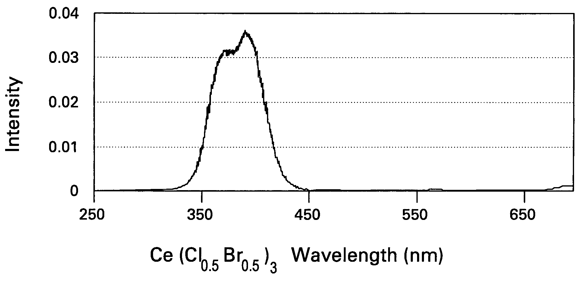
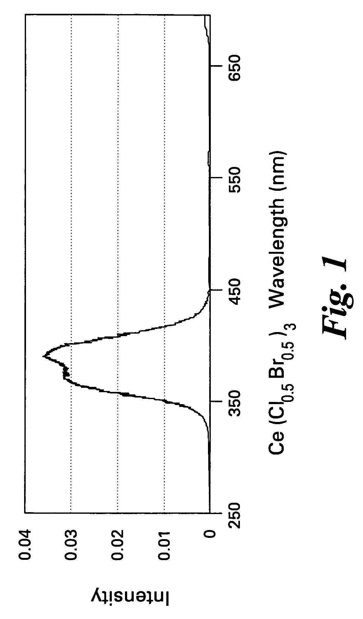
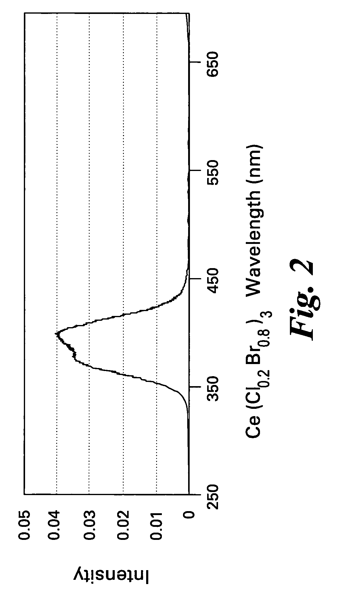
[0054]Three scintillator samples were prepared, and then examined for light output analysis. Each composition was prepared by dry-mixing various portions of cerium chloride and cerium bromide. (All materials were commercially-obtained). Mixing was carried out in an agate mortar and pestle. The uniform mixture was then transferred to an aluminum crucible, and fired at a temperature of about 600° C. The heating atmosphere was a mixture of 0.5% hydrogen and 99.5% nitrogen.

[0055]In sample A, the molar ratio of cerium chloride to cerium bromide was 50:50. In sample B, the molar ratio of cerium chloride to cerium bromide was 20:80. In sample C, the molar ratio of cerium chloride to cerium bromide was 10:90.

[0056]The emission spectrum for each sample was determined under X-ray excitation, using an optical spectrometer. FIGS. 1, 2 and 3 corre...


PUM

PropertyMeasurementUnit
energyaaaaaaaaaa
decay timeaaaaaaaaaa
temperatureaaaaaaaaaa

Abstract

A scintillator composition is disclosed, containing a solid solution of at least two cerium halides. A radiation detector for detecting high-energy radiation is also described herein. The detector includes the scintillator composition mentioned above, along with a photodetector optically coupled to the scintillator. A method for detecting high-energy radiation with a scintillation detector is also described, wherein the scintillation crystal is based on a mixture of cerium halides.

Description

BACKGROUND OF THE INVENTION[0001]This invention generally relates to scintillator compositions, e.g., those which are useful for detecting gamma-rays and X-rays under a variety of conditions.[0002]Scintillator crystals are widely used in detectors for high-energy radiation, e.g. gamma-rays, X-rays, cosmic rays, and particles characterized by an energy level of greater than about 1 keV. The crystal is coupled with a light-detection means, i.e., a photodetector. When photons from a radionuclide source impact the crystal, the crystal emits light. The photodetector produces an electrical signal proportional to the number of light pulses received, and to their intensity. Scintillator crystals are in common use for many applications. Examples include medical imaging equipment, e.g., positron emission tomography (PET) devices; well-logging for the oil and gas industry, and various digital imaging applications.[0003]The specific composition of the scintillator is critical to the performance...

Claims


Application Information

Patent Timeline
Patent Type & Authority Patents(United States)
IPC IPC(8): G01T1/24C09K11/68
CPCC09K11/7719G01T1/2023G21K4/00C09K11/08
Inventor SRIVASTAVA, ALOK MANIDUCLOS, STEVEN JUDECOMANZO, HOLLY ANNDENG, QUNCLARKE, LUCAS LEMAR
Owner BAKER HUGHES INC
Why Eureka
Try Eureka