Method for handling semiconductor layers in such a way as to thin same

a technology of semiconductor layers and layers, applied in the direction of microstructural technology, electric devices, solid-state devices, etc., can solve the problems of reducing the thickness of wafers, affecting the thickness of structures, and affecting the effect of thickness

Inactive Publication Date: 2007-04-17
COMMISSARIAT A LENERGIE ATOMIQUE ET AUX ENERGIES ALTERNATIVES
View PDF19 Cites 25 Cited by
  • Summary
  • Abstract
  • Description
  • Claims
  • Application Information

AI Technical Summary

Problems solved by technology

At the moment it is extremely difficult to reduce the thickness of wafers to very small values (less than 100 μm), causing yield problems.
For such small thicknesses, the wafer becomes flexible and often breaks during the thinning operation before stresses have been relaxed.
Although this additional layer produces very strong bonding forces compatible with thinning, it modifies the thickness of the structure.
It is also very difficult to control the glue thickness present and its homogeneity on the wafer.
These characteristics cause a problem if uniform and precise thinning within a few micrometers is necessary.
Moreover, the use of glue introduces another problem if it is required to transfer the thin layer onto a final support after thinning, and eliminate the intermediate support that acts as a handle.
Two problems then arise.
The first is that the solvent is not always compatible with the final support, for example if the final support is a plastic smart card.
The second problem is that glue residues can remain that are sometimes difficult to remove.
However, the wafers on which electronic components are installed have a relief that makes it impossible to achieve the conditions required for direct wafer bonding.
This perfect planarisation is incompatible with wafers for which relief is necessary, particularly to maintain openings at component contact pads.
Furthermore, in their article on page 54 in their Materials Science and Engineering R report: “Wafer Direct Bonding: Tailoring Adhesion Between Brittle Materials”, A. PLOSSL et al. mention that if wafers are solidarised by a hydrophilic gluing, subsequent annealing (for example at 100° C.) makes their separation difficult.
However, prior art does not describe any method that can be used to reversibly glue a wafer including components and with a relief that has to be partly maintained, onto an intermediate part used as a handle, this bonding being such that the wafer can be thinned and that the thinned wafer can be manipulated on its handle.

Method used


Image

  • Method for handling semiconductor layers in such a way as to thin same
  • Method for handling semiconductor layers in such a way as to thin same
  • Method for handling semiconductor layers in such a way as to thin same

Examples


Embodiment Construction

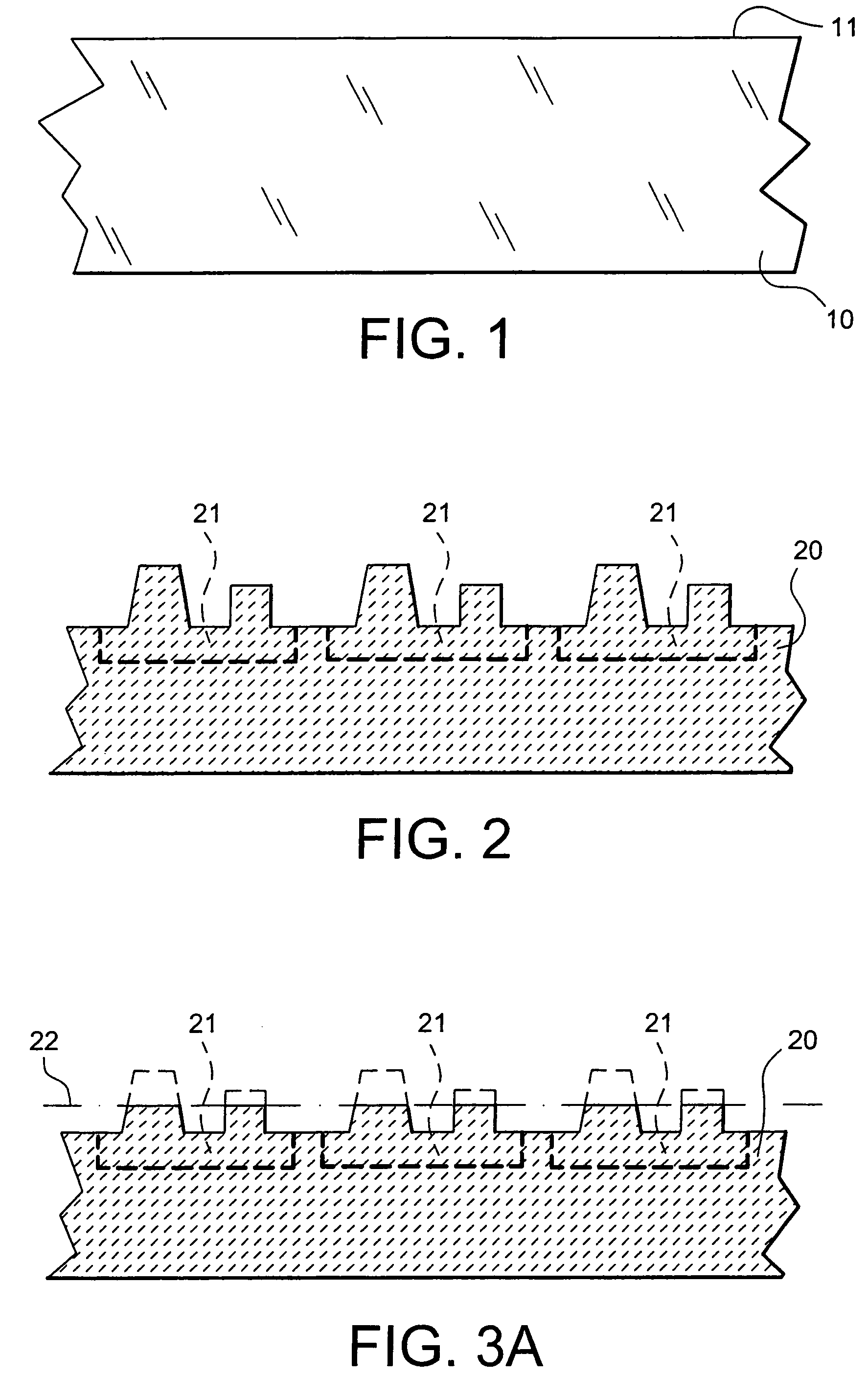
[0046]FIG. 1 is a cross-sectional view of a support handle 10, for example composed of a silicon or glass wafer. Glass has the advantage of being transparent, so that objects deposited on the back face can be inspected visually. The support handle 10 has a face 11 prepared to act as a bonding face.

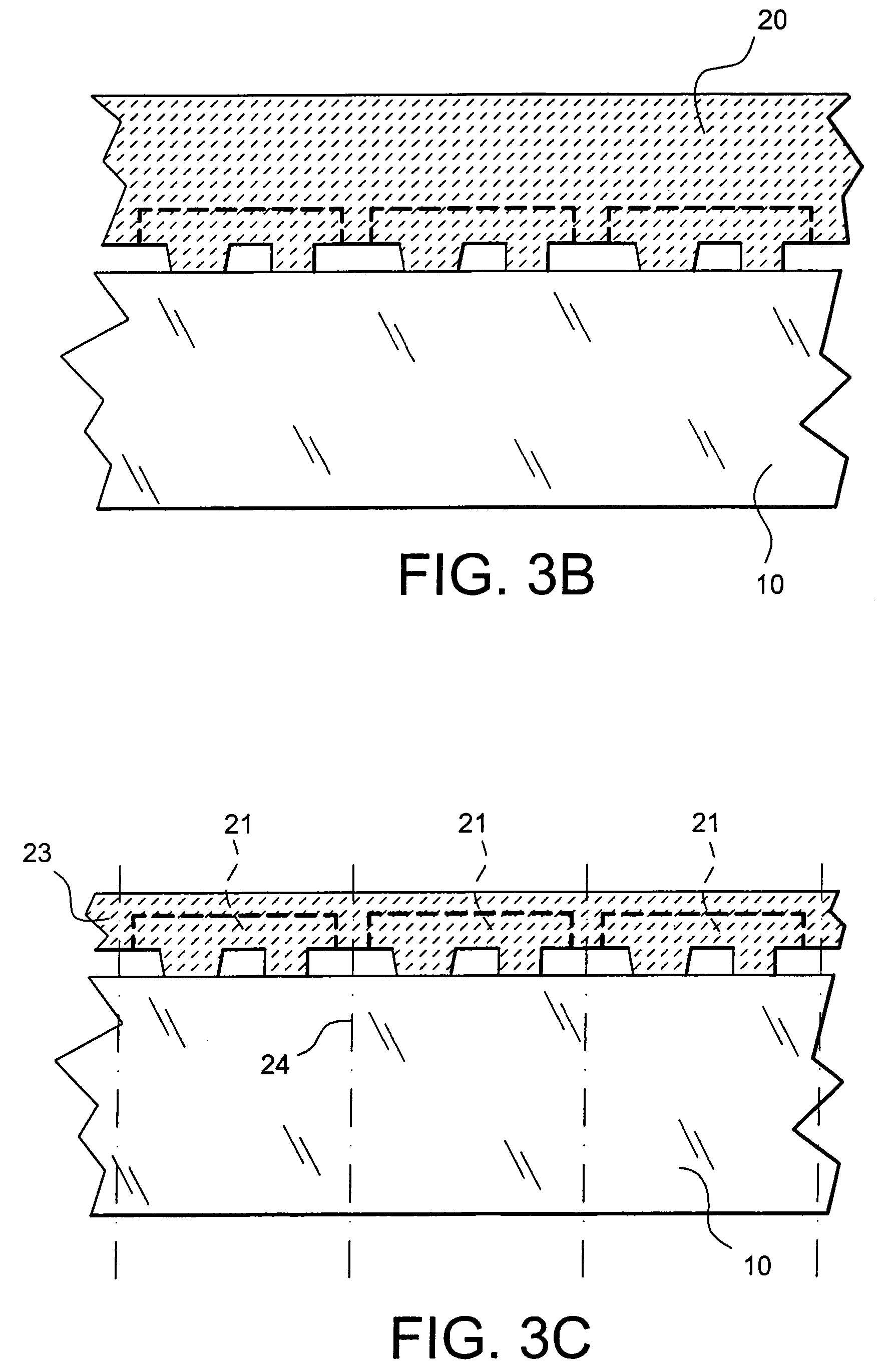
[0047]FIG. 2 is a cross-sectional view of a wafer 20 made of a semiconducting material, for example silicon. One of its main faces has been treated to make electronic components. FIG. 2 is a partial view showing three complete or incomplete components 21. Due to the presence of these components, the treated plane face has a large relief with several areas of different heights and different roughnesses. When the wafer comprises complete components, part of this relief corresponds to the presence of openings used to connect to electrical contacts.

[0048]In general, the chemical nature of the wafers to be bonded by molecular bonding, chemical cleaning before bonding and the bonding consolidati...


PUM


Abstract

This invention relates to a method for making a thin layer starting from a wafer comprising a front face with a given relief, and a back face, comprising steps consisting of:a) obtaining a support handle with a face acting as a bonding face;b) preparing the front face of the wafer, this preparation including incomplete planarisation of the front face of the wafer, to obtain a bonding energy E0 between a first value corresponding to the minimum bonding energy compatible with the later thinning step, and a second value corresponding to the maximum bonding energy compatible with the subsequent desolidarisation operation, the bonding energy E0 being such that E0=α.E, where E is the bonding energy that would be obtained if the front face of the wafer was completely planarised, α is the ratio between the incompletely planarised area of the front face of the wafer and the area of the front face of the wafer if it were completely planarised;c) solidarising the front face of the wafer on the bonding face of the support handle, by direct bonding;d) thinning the wafer starting from its back face until the thin layer is obtained;e) transferring the thin layer onto a usage support, involving separation from the support handle.

Description

CROSS-REFERENCE TO RELATED APPLICATION[0001]This application claims priority based on International Patent Application No. PCT / FR03 / 00954, entitled “Method for Handling Semiconductor Layers in Such a Way As to Thin Same” by Bernard Aspar. Marc Zussy and Jean-Frederic Clerc, which claims priority of French Application No. 02 03909, filed on Mar. 28, 2002, and which was not published in English.TECHNICAL DOMAIN[0002]Needs for electronic components that are very thin (between a few μm and a few tens of μm) are increasing. These ultra thin components have many advantages, principally their small size and considerable flexibility of use. For example, this type of electronic component can be integrated on plastic or paper supports. The first application is for smart cards and electronic labels. Ultra-thin electronic components are also increasingly in demand in domains such as encapsulation in order to make circuits in ultra-flat boxes.[0003]These ultra-thin components are also essential ...

Claims


Application Information

Patent Timeline
Patent Type & Authority Patents(United States)
IPC IPC(8): H01L21/78H01L21/02H01L27/12H01L21/20H01L21/68H01L21/762
CPCB81C1/0038H01L21/2007H01L21/6835H01L21/76251B81C2201/0191B81C2203/036H01L2221/68359Y10S438/977
Inventor ASPAR, BERNARDZUSSY, MARCCLERC, JEAN-FREDERIC
Owner COMMISSARIAT A LENERGIE ATOMIQUE ET AUX ENERGIES ALTERNATIVES
Why Eureka
Try Eureka