Formation of boride barrier layers using chemisorption techniques

a technology of boride barrier layer and chemisorption, which is applied in the direction of coating, chemical vapor deposition coating, metallic material coating process, etc., can solve the problems of increasing the resistivity of the interconnection layer, affecting the reliability of the integrated circuit, and affecting the resulting integrated circui

Inactive Publication Date: 2007-04-24
APPLIED MATERIALS INC
View PDF674 Cites 405 Cited by
  • Summary
  • Abstract
  • Description
  • Claims
  • Application Information

AI Technical Summary

Problems solved by technology

For the current subhalf-micron (0.5 μm) generation of semiconductor devices, any microscopic reaction at an interface between interconnection layers can cause degradation of the resulting integrated circuits (e.g., increase the resistivity of the interconnection layers).
However, when Cl-based chemistries are used to form boride barrier layers, reliability problems can occur.
A high chlorine content is undesirable because the chlorine may migrate from the boride barrier layer into adjacent interconnection layers, which can increase the contact resistance of such interconnection layers and potentially change the characteristics of integrated circuits made therefrom.

Method used


Image

  • Formation of boride barrier layers using chemisorption techniques
  • Formation of boride barrier layers using chemisorption techniques
  • Formation of boride barrier layers using chemisorption techniques

Examples


Embodiment Construction

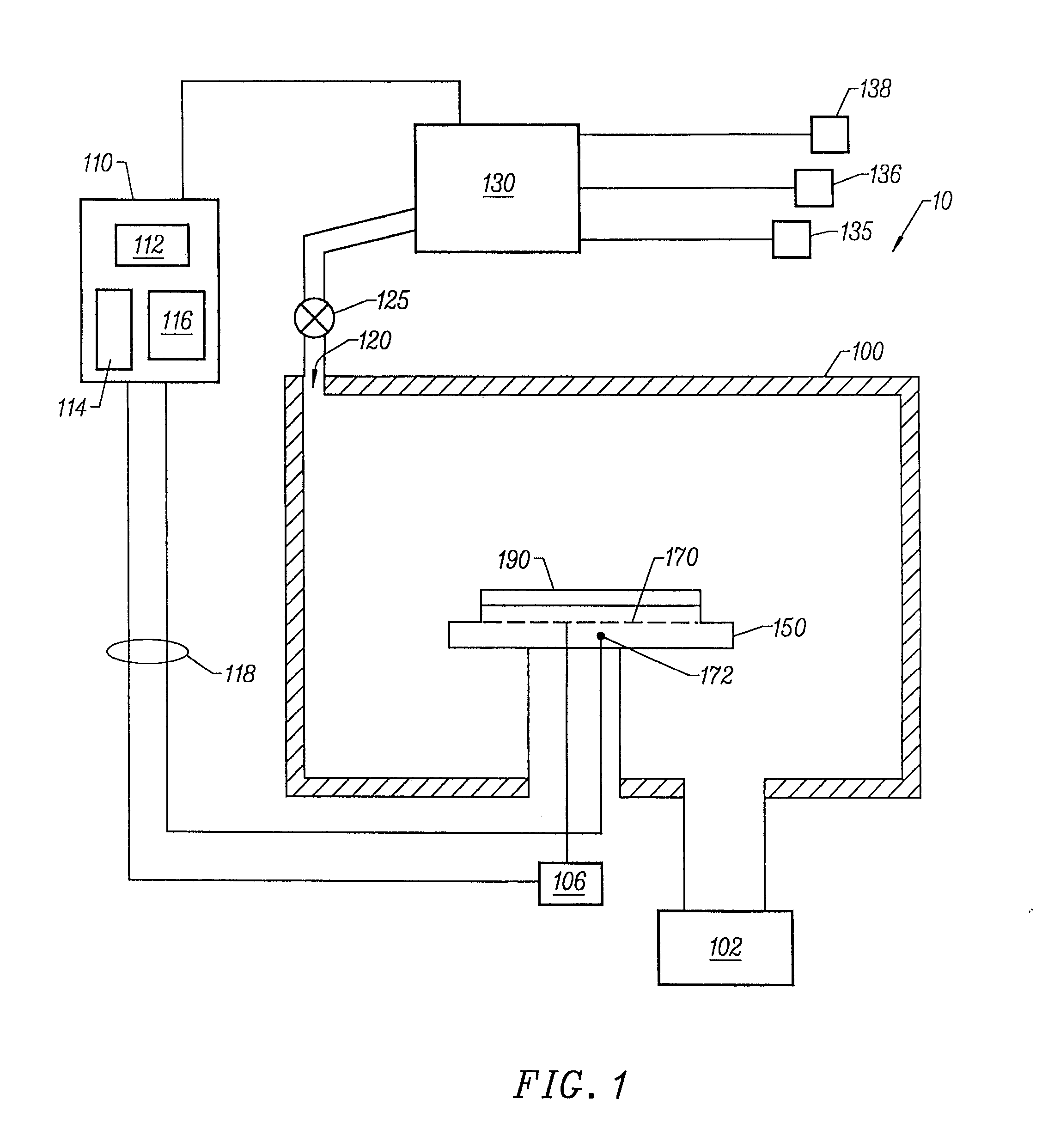
[0021]FIG. 1 depicts a schematic illustration of a wafer processing system 10 that can be used to form boride barrier layers in accordance with embodiments described herein. The system 10 comprises a process chamber 100, a gas panel 130, a control unit 110, along with other hardware components such as power supplies 106 and vacuum pumps 102. The salient features of process chamber 100 are briefly described below.

Chamber 100

[0022]The process chamber 100 generally houses a support pedestal 150, which is used to support a substrate such as a semiconductor wafer 190 within the process chamber 100. Depending on the specific process, the semiconductor wafer 190 can be heated to some desired temperature prior to layer formation.

[0023]In chamber 100, the wafer support pedestal 150 is heated by an embedded heater 170. For example, the pedestal 150 may be resistively heated by applying an electric current from an AC power supply 106 to the heater element 170. The wafer 190 is, in turn, heated...


PUM

PropertyMeasurementUnit
temperatureaaaaaaaaaa

Abstract

A method of forming a boride layer for integrated circuit fabrication is disclosed. In one embodiment, the boride layer is formed by chemisorbing monolayers of a boron-containing compound and one refractory metal compound onto a substrate. In an alternate embodiment, the boride layer has a composite structure. The composite boride layer structure comprises two or more refractory metals. The composite boride layer is formed by sequentially chemisorbing monolayers of a boron compound and two or more refractory metal compounds on a substrate.

Description

CROSS-REFERENCE TO RELATED APPLICATIONS[0001]This application is a continuation of U.S. patent application Ser. No. 10 / 387,990, filed Mar. 13, 2003, which is now U.S. Pat. No. 6,831,004 which is a continuation of U.S. Ser. No. 09 / 604,943 U.S. Pat. No. 6,620,723, filed Jun. 27, 2000, which are both herein incorporated by reference.BACKGROUND OF THE INVENTION[0002]1. Field of the Invention[0003]The present invention relates to the formation of boride barrier layers and, more particularly to boride barrier layers formed using chemisorption techniques.[0004]2. Description of the Related Art[0005]In the manufacture of integrated circuits, barrier layers are often used to inhibit the diffusion of metals and other impurities into regions underlying such barrier layers. These underlying regions may include transistor gates, capacitor dielectric, semiconductor substrates, metal lines, as well as many other structures that appear in integrated circuits.[0006]For the current subhalf-micron (0....

Claims


Application Information

Patent Timeline
Patent Type & Authority Patents(United States)
IPC IPC(8): H01L21/44C23C16/38C23C16/44C23C16/455H01L21/285H01L21/768
CPCC23C16/38C23C16/45529C23C16/45531C23C16/45553H01L21/28562H01L21/76843H01L21/76846H01L21/76877
Inventor BYUN, JEONG SOOMAK, ALFRED
Owner APPLIED MATERIALS INC
Why Eureka
Try Eureka