Optical communications using heterodyne detection

a detection and heterodyne technology, applied in the field of optical fiber communication, can solve the problems of limiting the performance and/or utility of current optical fiber systems, further intensifying this demand, etc., and achieves the effects of increasing the sensitivity of the receiver subsystem, reducing power consumption, and prolonging transmission length

Inactive Publication Date: 2007-04-24
XYLON LLC
View PDF46 Cites 39 Cited by
  • Summary
  • Abstract
  • Description
  • Claims
  • Application Information

AI Technical Summary

Benefits of technology

[0018]The present invention has many advantages. For example, the use of heterodyne detection increases the sensitivity of the receiver subsystem. Thus, either lower power optical signals or longer transmission lengths may be supported. Heterodyne detection also results in greater wavelength selectivity (for example, as compared to direct detection). This allows the use of less costly components elsewhere (for example, a conventional optical power splitter rather than a WDM de...

Problems solved by technology

Upcoming widespread deployment of new bandwidth-intensive services, such as xDSL, will only further intensify this demand.
However, current optical fiber systems also suffer from drawbacks which limit their performance and/or utility.
As a result, the components may not recombine correctly at the receiver, thus distorting or degrading the original signal.
In fact, at certain frequencies, the dispersive effect may result in destructive interference at the receiver, thus effectively preventing the transmission of signals at these frequencies.
However, the additional equipment results in additional power loss (e.g., insertion loss) as well as in additional cost, and different compensators will be required for different types and lengths of fiber.
Other fiber effects, such as fiber nonlinearities, can similarly degrade performance.
MZMs, however, are inherently nonlinear devices.
As a final example, optical fibers have an inherently large bandwidth available for the transmission of data, but constructing transmitters and receivers which can take advantage of this large bandwidth can be problematic.
First, curren...

Method used


Image

  • Optical communications using heterodyne detection
  • Optical communications using heterodyne detection
  • Optical communications using heterodyne detection

Examples


Embodiment Construction

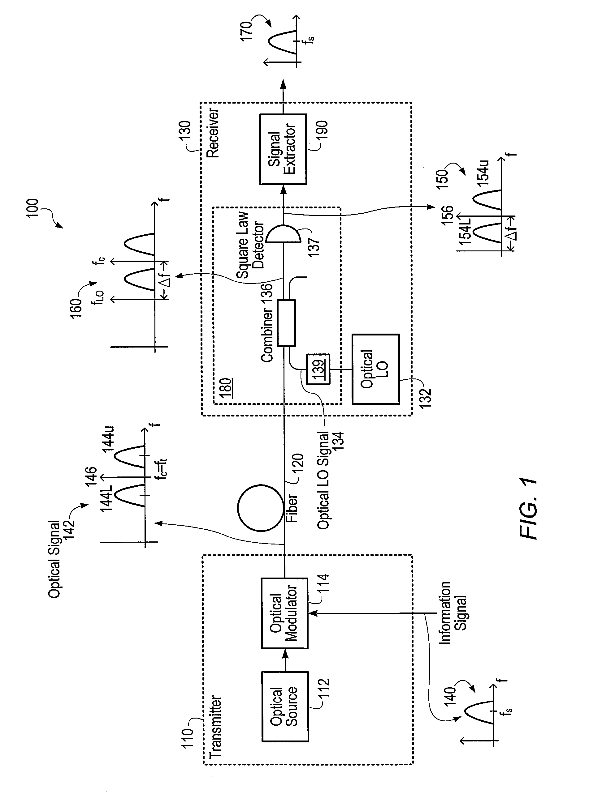
[0037]FIG. 1 is a diagram of a system 100 according to the present invention. System 100 includes a transmitter 110 coupled to a receiver 130 by optical fiber 120. The receiver 130 preferably includes a heterodyne detector 180 coupled to a signal extractor 190. System 100 is used to transmit an information signal from transmitter 110 to receiver 130 via fiber 120.

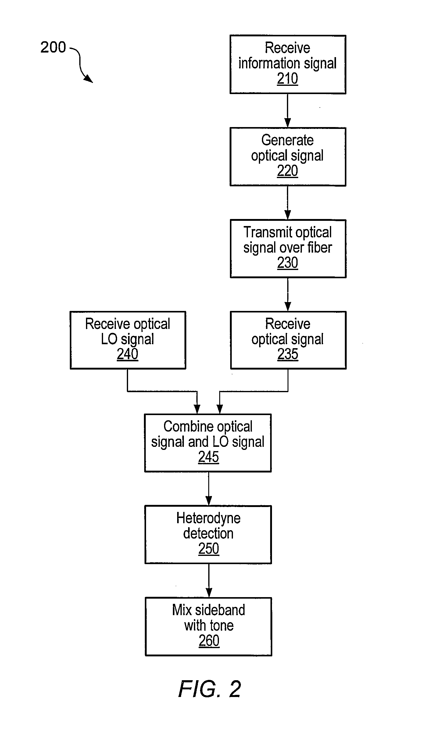
[0038]With reference to the flow diagram of FIG. 2 as well as to FIG. 1, system 100 operates as follows. The frequency spectrum of an example information signal is shown by spectrum 140, which is characterized by a frequency fS. The frequency fS could be zero, for example, if the information signal is based on on-off keying. The information signal 140 may be any of a variety of signals. For example, it may be a single high speed data stream. Alternately, it may contain a number of data streams which are time-division multiplexed together, for example, if 64 OC-3 data streams are combined together to form a single OC-192 sig...


PUM


Abstract

An optical communications system includes a receiver subsystem with at least two heterodyne receivers. The receiver subsystem receives a composite optical signal having two or more subbands of information and corresponding tones. An optical splitter splits the composite optical signal into optical signals. Each optical signal includes a subband(s) and corresponding tone. Each heterodyne receiver receives an optical signal. The receiver includes a heterodyne detector coupled to a signal extractor. The heterodyne detector mixes the optical signal with an optical local oscillator to produce an electrical signal which includes a frequency down-shifted version of the subband and the tone of the optical signal. The signal extractor mixes the frequency down-shifted subband with the frequency down-shifted tone to produce a frequency component containing the information.

Description

CROSS-REFERENCE TO RELATED APPLICATION[0001]This application is a continuation-in-part of pending U.S. patent application Ser. No. 09 / 474,659, “Optical Communications System Using Heterodyne Detection”, by Ting K. Yee and Peter H. Chang, filed Dec. 29, 1999.[0002]This application relates to pending U.S. patent application Ser. No. 09 / 405,367, “Optical Communications Networks Utilizing Frequency Division Multiplexing,” by Michael W. Rowan, et al., filed Sep. 24, 1999; which is a continuation-in-part of pending U.S. patent application Ser. No. 09 / 372,143, “Optical Communications Utilizing Frequency Division Multiplexing and Wavelength-Division Multiplexing,” by Peter H. Chang, el al., filed Aug. 20, 1999; which is a continuation-in-part of U.S. patent application Ser. No. 09 / 229,594, “Electrical Add-Drop Multiplexing for Optical Communications Networks Utilizing Frequency Division Multiplexing,” by David B. Upham, et al., filed Jan. 13, 1999; which is a continuation-in-part of U.S. pa...

Claims


Application Information

Patent Timeline
IPC IPC(8): H04B10/145H04B10/04H04B10/06H04B10/148H04B10/207H04J1/04H04J1/06H04J1/08H04J14/02H04B10/272
CPCH04B10/50H04B10/61H04B10/6151H04B10/64H04J14/005H04J14/02H04J14/0298
Inventor YEE, TING KCHANG, PETER H
Owner XYLON LLC
Why Eureka
Try Eureka