Arrangement for illumination and/or detection in a microscope

a microscope and arrangement technology, applied in the field of laser scanning microscopes, can solve the problem that the arrangement is not flexible enough to be adapted to the specimen spectrum, and achieve the effects of improving the spatial resolution of the entire microscope system, compact system construction, and improving beam quality

Inactive Publication Date: 2007-05-01
CARL ZEISS MICROSCOPY GMBH
View PDF3 Cites 13 Cited by
  • Summary
  • Abstract
  • Description
  • Claims
  • Application Information

AI Technical Summary

Benefits of technology

[0012]In a variant, the excitation radiation can advantageously be coupled into the system via the mirror pixels corresponding to the excitation (FIGS. 3a, b). The need for a main beam splitter (DBS) is therefore circumvented and an appreciably more compact system construction can be realized. In addition, the excitation radiation in this case automatically passes through the detection pinhole as illumination pinhole, which leads to an improvement in beam quality (spatial filtering) and therefore improved spatial resolution of the entire microscope system. In addition, by means of oscillating the mirror utilized for reflecting the excitation radiation between two possible mirror positions, the illumination intensity can be adjusted in an almost continuous manner and can be changed in a synchronized manner with respect to the scan pixels (shading compensation, intensity modulation, etc.).
[0013]Further, a freely programmable confocal diaphragm (pinhole) can be realized (FIG. 4) by means of another switching mirror array which is introduced in a conjugate plane to the object plane. This pinhole is freely programmable with respect to shape and size (adjustable confocal volume) as well as with respect to lateral position, which increases the flexibility of the system and is a great advantage for the adjustment of the optical system (autoadjustment of pinhole). In addition, in multichannel applications, the pinhole size can be synchronized with the spectral band detected at that instant in order that optical sections independent from the wavelength can be realized with the confocal microscope. In addition, the pinhole size can also be advantageously adapted to the intensity of the fluorescent radiation when various fluorescences of very different intensity are present simultaneously in the specimen and are to be detected.
[0014]In an advantageous variant, a curved grating can be used, which curved grating likewise takes over the collimation and the dispersion of the radiation to be detected and accordingly results in a reduced quantity of optical components (FIG. 5). The structural size of the arrangement according to the invention in its entirety is accordingly advantageously reduced. Above all, this leads to a greater optical stability of the detection system.
[0015]In a variant, the optical grating can be replaced by a prism. In this way, an increase in the efficiency of the optical system is potentially possible (FIG. 6), particularly in the detection of unpolarized light.
[0019]Gratings, prisms or combinations thereof, for example, can be used as dispersive media in the constructions described above. By using these components in a double-pass configuration, the effective dispersion can be doubled and a particularly compact construction of the laser scanning microscope can accordingly realized in an advantageous manner.

Problems solved by technology

However, since only a finite number of dielectric splitters and filters can be received in every holder and the spectral characteristics of every individual splitter / filter are determined in the process of their manufacture, this arrangement is not flexible enough to be adapted to the specimen spectrum in an optimum manner in many cases of application (FIG. 1).

Method used


Image

  • Arrangement for illumination and/or detection in a microscope
  • Arrangement for illumination and/or detection in a microscope
  • Arrangement for illumination and/or detection in a microscope

Examples


Embodiment Construction

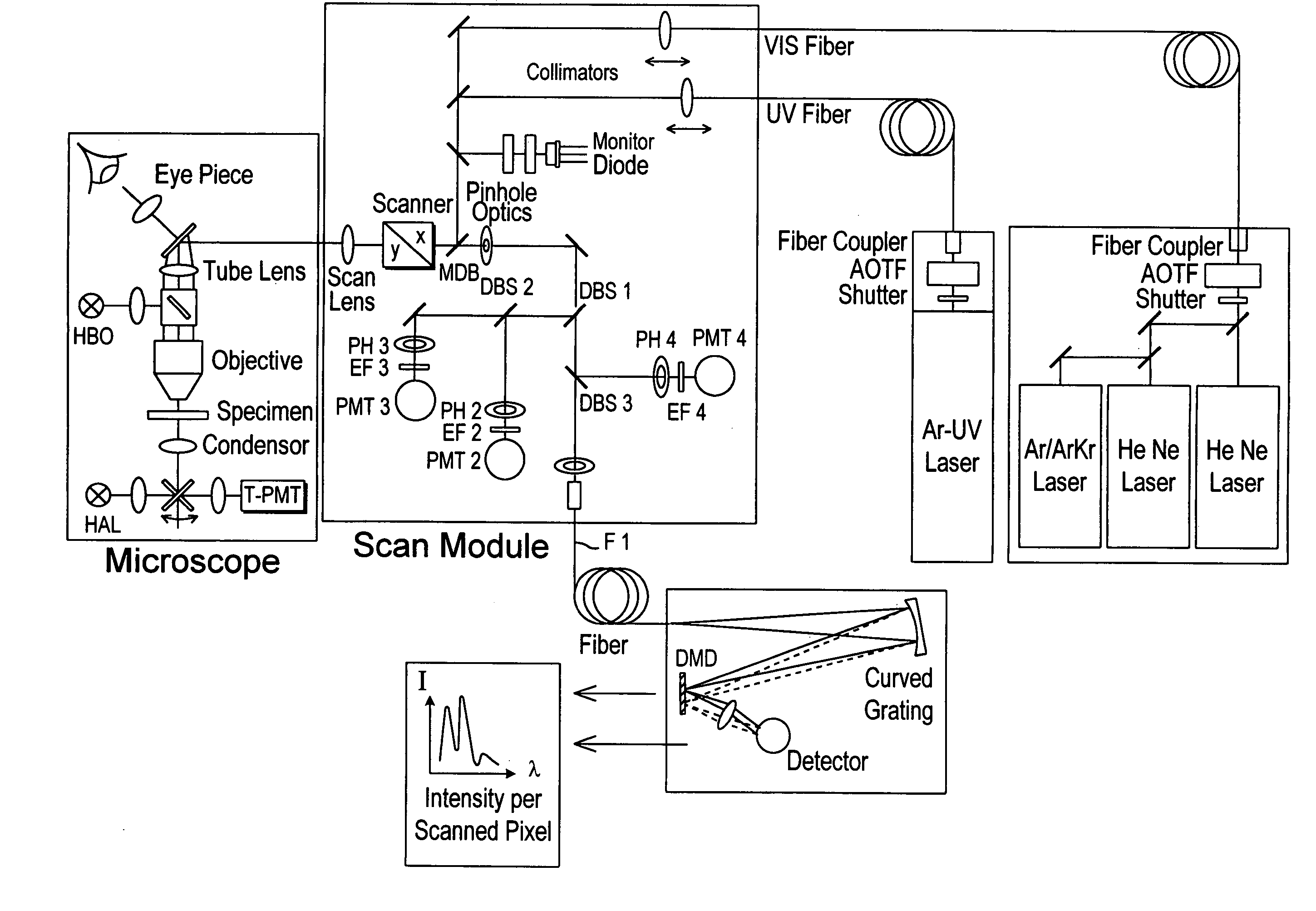
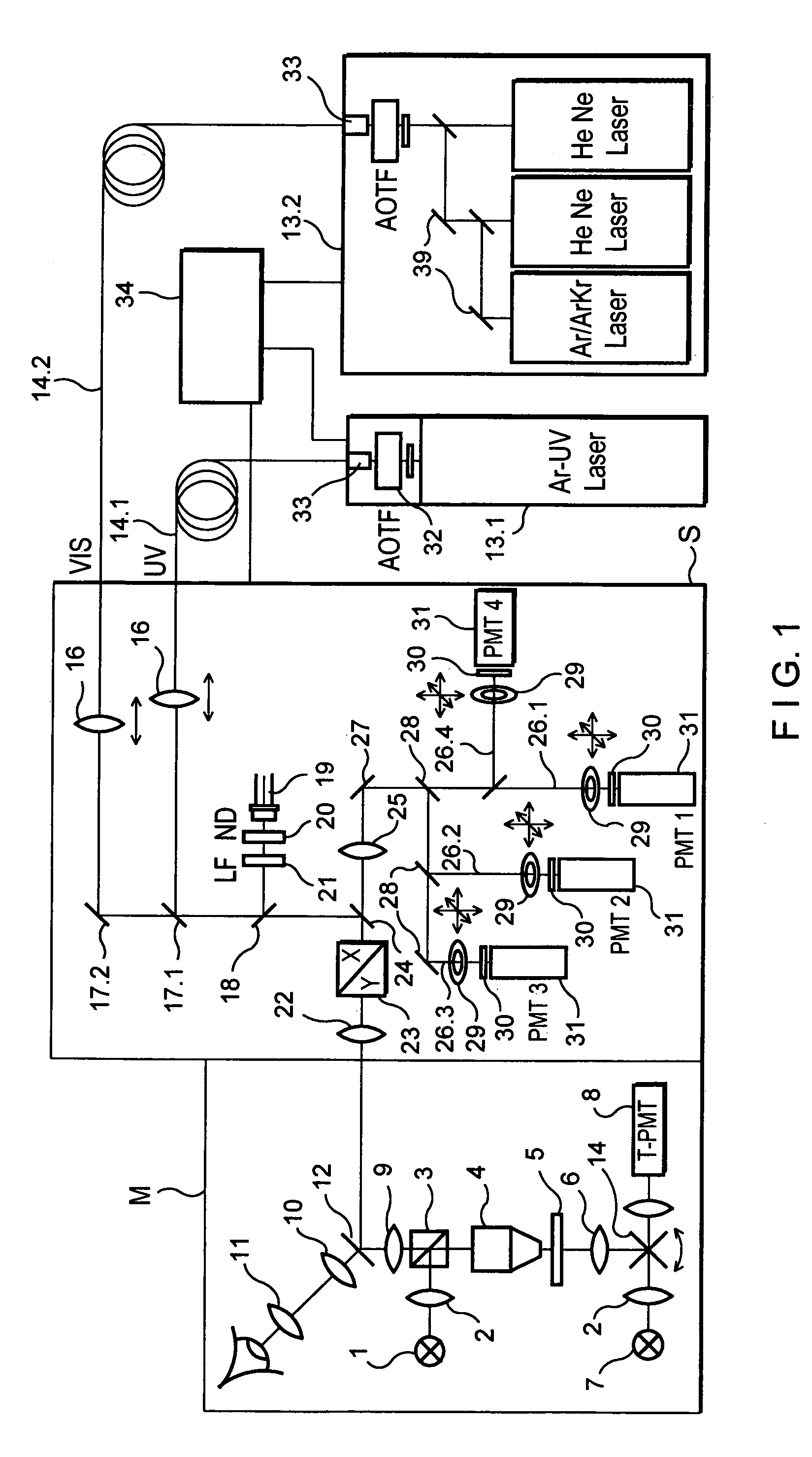
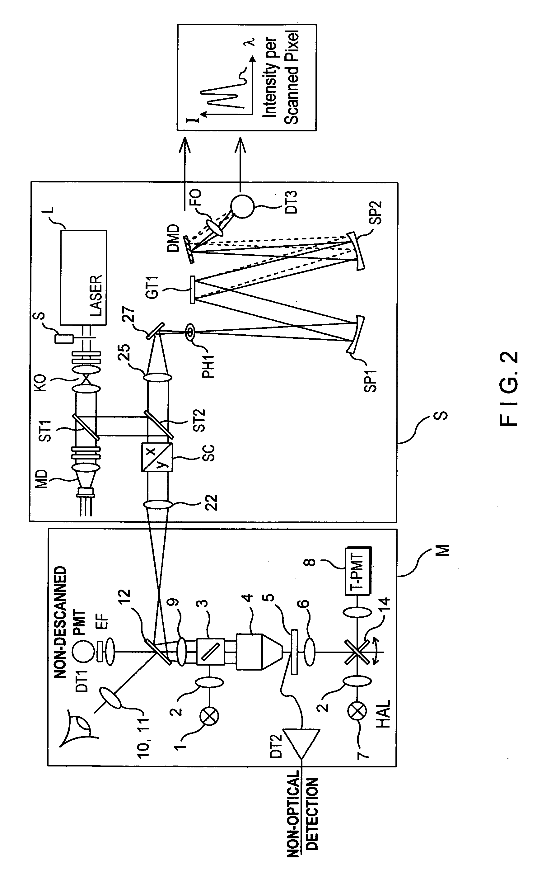
[0034]FIG. 1 shows schematically a microscope unit M and a scan head S which have a common optical interface via an intermediate image and form an LSM.

[0035]The scan head S can be mounted on the phototube of an upright microscope as well as on a lateral output of an inverse microscope.

[0036]The drawings show a microscope beam path which is switchable between incident light scanning and transmitted light scanning by means of a swivelable mirror 14, with a light source 1, illumination optics 2, beam splitter 3, objective 4, specimen stage 5, condenser 6, light source 7, receiver arrangement 8, a tube lens 9, an observation beam path with a tube lens 10 and an eyepiece 11, and a beam splitter / mirror 12 for coupling in the scanning beam. A laser module 13.1, 13.2 holds the laser and is connected via monomode light-conducting fibers 14.1, 14.2 with the laser input coupling unit of the scan head S.

[0037]The coupling of radiation into the light-conducting fibers 14.1, 14.2 is carried out b...


PUM


Abstract

A laser scanning microscope comprises at least one selectively switchable micro-mirror arrangement (DMD) in the illumination beam path and / or detection beam path which is used for the wavelength selection of dispersively divided illumination and / or object light such as reflection, fluorescence.

Description

CROSS-REFERENCE TO RELATED APPLICATIONS[0001]This is a continuation of U.S. application Ser. No. 09 / 295,555, filed Apr. 21, 1999 now abandoned, which claims priority to German Application No. 198 35 072.4, filed Aug. 4, 1998, all of which are incorporated herein by reference.BACKGROUND OF THE INVENTION[0002]a) Field of the Invention[0003]The invention is directed to a laser scanning microscope comprising a laser unit, scanning means, a microscope stand, a detection unit and a control / receiving unit, wherein the spectral characteristics of the detection unit can be freely programmed by a switching mirror array integrated in a monochromator. The switching mirror array (one- or two-dimensional) can be constructed, for example, as a DMD (Digital Mirror Device or switchable-mirror arrangement). The laser scanning microscope according to the invention enables different operating modes. On the one hand, the emitted spectrum can be detected with high resolution on every scanned pixel (in th...

Claims


Application Information

Patent Timeline
Patent Type & Authority Patents(United States)
IPC IPC(8): G02B21/06G02B21/00G02B21/16G02B26/08
CPCG02B21/002G02B21/0032G02B21/06G02B26/0833G02B26/0841
Inventor WEYH, THOMASSIMON, ULRICHSCHOEPPE, GUENTERWOLLESCHENSKY, RALFSTOCK, MICHAEL
Owner CARL ZEISS MICROSCOPY GMBH
Why Eureka
Try Eureka