Exposure method and apparatus

Inactive Publication Date: 2007-05-15
CANON KK
View PDF37 Cites 56 Cited by
  • Summary
  • Abstract
  • Description
  • Claims
  • Application Information

AI Technical Summary

Benefits of technology

[0009]Accordingly, it is an exemplary object of the present invention to provide an exposure method and apparatus that can expose, without exchanging a mask, a contact hole pattern that has a fine hole diameter (e.g., of 0.15 μm

Problems solved by technology

Thus, it is difficult for the normal exposure to form a pattern of 0.15 μm or less onto a wafer.
As a result, the diffracted light can neither pass the pupil in the projection lens nor resolve.
However, a prior art phase shift mask has not yet sufficiently exposed, at one time with high resolution, a contact hole pattern blended with a contact hole line and an isolated contact hole.
It is, on the other

Method used


Image

  • Exposure method and apparatus
  • Exposure method and apparatus
  • Exposure method and apparatus

Examples


example 1

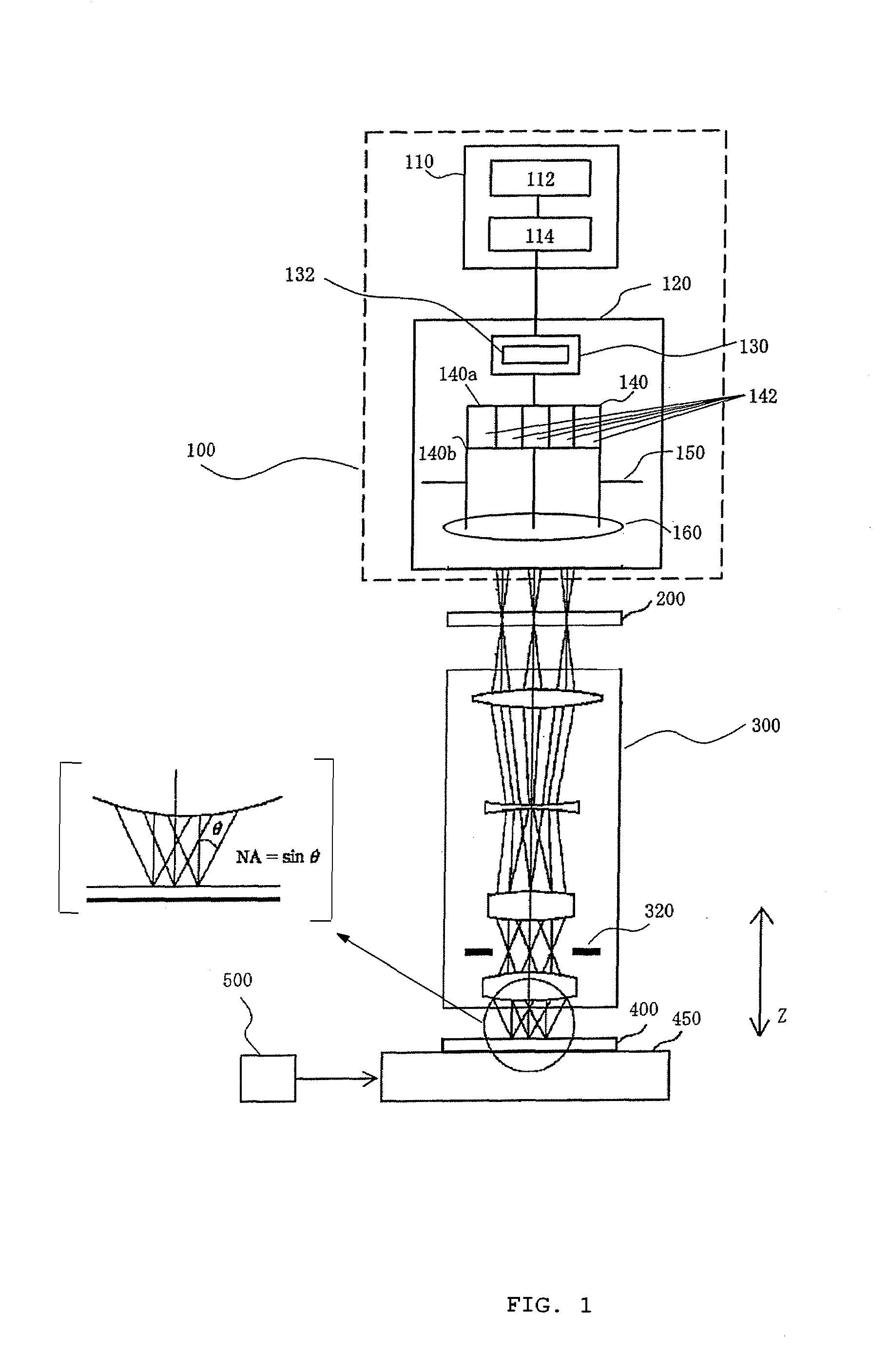
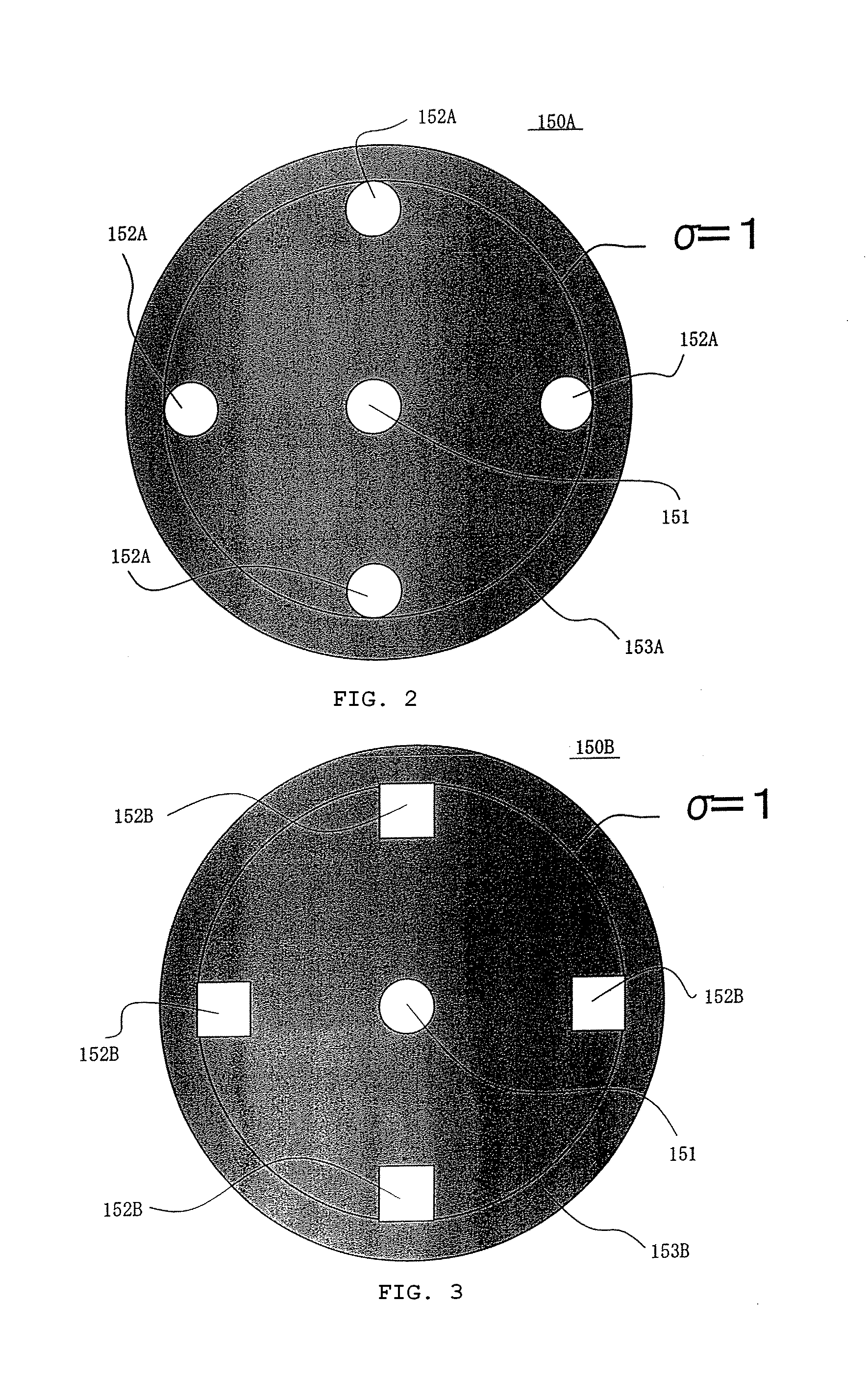
[0154]The example 1 uses the binary mask 200 shown in FIG. 8, KrF excimer (with a wavelength of 248 nm) as the laser 112 and the projection optical system of NA=0.60 for the exposure apparatus. The mask 200 sets a hole diameter of the desired contact holes 210 to be 150 nm, which is larger than a hole diameter of the dummy contact holes 220 by only 30 nm. The aperture stop 150 uses the aperture stop 150A shown in FIG. 2 while setting σ of the illumination light having its peak near the optical axis (in other words, brought about by the circle 151) to be 0.2 and σ of the illumination light having its peak off the axis (in other words, brought about by four circles 152A) to be 0.9. The intensity ratio between small σ illumination light and large σ illumination light is set to be 0.9 to 1 by the exposure-amount regulator 132.

[0155]The exposure result at this time is shown in FIG. 11. The figure shows the image-forming characteristics when the image-forming position adjuster 500 moves, ...

example 2

[0156]The embodiment 2 uses the phase shift mask 200A shown in FIG. 9. In other respects (in other words, the structure of the exposure apparatus, illumination conditions, exposure amount, etc.), the same conditions were used as that in the example 1. The result at this time is shown in FIG. 13. It will be understood that a number of improvements have been made compared with the binary mask 200.

example 3

[0157]The example 3 is the same as the example 1 or 2 except that the mask 200B shown in FIG. 10 was used. This example makes a hole diameter of dummy contact holes 260 adjacent to desired contact holes 210, smaller by about 20 nm (therefore, about 100 nm) than that of other dummy contact holes 230. Control over the intensity of dummy patterns between the desired patterns of contact holes 210 improves the exposure amount. It is fairly effective to the improvement of the image-forming performance to automatically reduce the hole diameter of a dummy contact hole 260 adjacent to a desired contact hole 210, but the optimization may depend upon the number of adjacent holes and the distance in-between.


PUM


Abstract

An exposure method comprising the steps of forming onto a mask that arranges a pattern of a contact hole and a plurality of patterns each being smaller than the contact hole pattern, and illuminating the mask using plural kinds of light so as to resolve the desired pattern without the smaller patterns on a target via a projection optical system.

Description

BACKGROUND OF THE INVENTION[0001]The present invention relates generally to exposure, and more particularly to exposure apparatuses and methods, device fabricating methods, and devices fabricated from an object to be exposed or a target object. The exposure apparatus and method are used to fabricate various devices including semiconductor chips such as ICs and LSIs, display devices such as liquid crystal panels, sensing devices such as magnetic heads, and image pick-up devices such as CCDs, as well as fine contact hole patterns used for micromechanics. Here, the micromechanics is technology for applying the semiconductor IC fabricating technique for fabrications of a fine structure, thereby creating an enhanced mechanical system that may operate at a level of micron.[0002]A photolithography process uses an exposure apparatus to transfer a mask pattern onto a photosensitive material (resist) which is applied to a silicon wafer, glass plate, etc. (simply called “wafer” hereinafter), a...

Claims


Application Information

Patent Timeline
IPC IPC(8): G03F7/20G03F1/00
CPCG03F1/144G03F1/30G03F7/70091G03F7/70466G03F1/36G03F7/70125G03F7/20
Inventor SAITOH, KENJISUZUKI, AKIYOSHIYAMAZOE, KENJI
Owner CANON KK
Why Eureka
Try Eureka