
Adaptively controlled footwear

Inactive Publication Date: 2007-05-22
PROMDX TECH
View PDF579 Cites 261 Cited by
  • Summary
  • Abstract
  • Description
  • Claims
  • Application Information

AI Technical Summary

Benefits of technology

[0032]A particular advantage accrues from control over energy release. In a traditional design, in order to provide a sufficiently damped response to avoid ringing and instability, a relatively high degree of energy dissipation was required. This is because a traditional design does not provide asymmetry in energy absorption and release, thus requiring a compromise, since release of the absorbed energy shortly after its absorption would be undesirable. The design of Demon, U.S. Pat. No. 5,813,412, on the other hand, provides controlled asymmetry, but in a purely dissipative manner, thereby precluding efficient energy recovery. On the other hand, according to an embodiment of the present invention, instead of dissipating the principal cushioning energy, it is stored for later release. Thus, a desired damping profile may be achieved, without necessarily dissipating the energy as would be required in a time invariant system, or in a system which lacks a special energy absorption element.
[0141]It is noted that, in another configuration, the energy storage and recovery system may be employed to assist disabled persons with impaired gait. Thus, for example, the stored energy may be applied to a cable or strap mechanism to assist in lifting the off the ground during a toe-off phase of gait. By applying a torque to dorsiflex the foot, for example by applying a tensile force between a point above the ankle and the top of the toe, dragging of the toe and associated limping can be reduced. The trigger for applying this torque is, for example, a forward inclination of the shoe, a maximum bending of the sole, a slip of the toe against the ground, or a rapid release of pressure on the toe indicating a foot lift.

Problems solved by technology

However, due to the rigors of various athletic events, and because the human foot tends to swell and contract with varying levels of activity, it is very difficult for the individual to obtain a consistent fit from one use to the next, or to recognize the difference in their performance, based upon a pressure setting for the air bladders that is merely sensed by the foot.
The theory of intelligent adaptive surfaces provides that too high a pressure applied to an area of skin may cause discomfort or produce medical problems.
Actuators, provided under the surface, deform the surface to adjust the applied pressure and potentially increase the contact patch.
However, efficient active miniature (<300 W thermal transfer capacity) cooling systems pose many design compromises, and few optimal designs are available.
However, such systems require a significant electrical current.
First, heat in an object to be cooled may be lost by transferring heat energy from a hotter mass to a cooler mass, which may be an active, facilitated or conduction process.
Thermoelectric junctions may also be used to cool, although their power efficiency is relatively low.
The inventor also notes that “as is recognized in the art, it is not possible to predict the formation of azeotropes.
This fact obviously complicates the search for new azeotrope compositions” (col.

Method used


Image

  • Adaptively controlled footwear
  • Adaptively controlled footwear
  • Adaptively controlled footwear

Examples


example 1

Cooled Footwear

[0160]In garments or footwear, the operating temperatures are generally about 30–45 degrees C. on the body side and about −20–+40 degrees C. on the external side. In general, cooling may be desired when the body temperature is above 37 degrees C. and the external temperature is above 10 degrees C. Below these temperatures, cooling by active or facilitated means may not be necessary or desirable.

[0161]It should also be noted that after a short period, footwear reaches a temperature steady state, with the metabolic heat from the foot transferred to the environment, so that the rate of production equals the rate of withdrawal. Therefore, in an active or facilitated heat removal system, the amount of heat to be radiated is of the same order of magnitude of heat shedding as a normal shoe. Thus, the radiator need not be very large in comparison to the shoe, nor operate at substantially elevated temperatures over that normally achieved in a shoe under normal circumstances.

[0...

example 2

Adaptive Fit Footwear, Pressurized Bladders in Upper

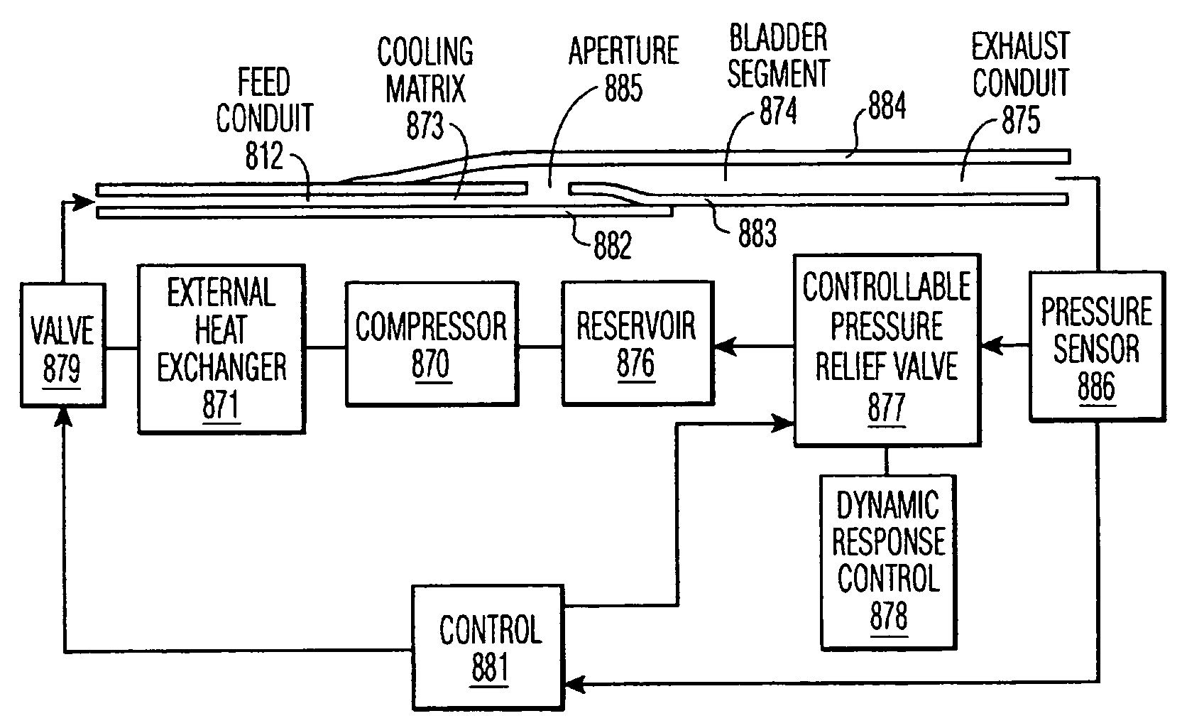
[0216]According to another embodiment of the invention, a set of inflatable bladders are formed in the footwear upper. These bladders may be inflated with air, refrigerant, or liquid. The bladders are formed of two layers of a high modulus polymer film, for example polyester film (e.g., Mylar®) with conduits formed integral to the heat sealing pattern to a control system, which is, for example, embedded in the sole. Advantageously, a cooling system is provided which removes heat from below the bladder system. Thus, according to one embodiment, a volatile refrigerant flows through a maze pattern segment formed between a first and second layer of heat-sealed film. The terminus of the maze pattern segment is an aperture formed through one of the film layers, leading to a bladder segment formed between a second and third layer of heat sealed film.

[0217]The bladder segment has a conduit formed by an elongated potential space between the...

example 3

Adaptive Fit Footwear, Adjustable Tensioners

[0230]As shown in FIGS. 18–30, footwear is provided with an upper fit controlled by a set of hydraulic actuators 701–705. These actuators 701–705 control the tension on a set of straps 707–711 on the upper, which assure a proper fit. The pressure in each actuator 701–705 is measured by a pressure sensor 767. A set of strain gages (not shown) integrated into the upper or straps 707–711 may also be used to determine the fit of the shoe 700.

[0231]The actuators 701–705 receive pressurized fluid from a hydraulic compressor 755, which selectively communicates to each actuator 701–705 through check valve 759, line 760 and rotary valve 761. The rotary valve 761 is driven by an electrical actuator, for example a shape memory actuator, controlled by the control module 754. A reservoir 756 is provided for hydraulic fluid, which is, for example, an ethylene glycol antifreeze or mineral oil. The strap 764, is noncompliant, and driven by the stretch of ...


PUM


Abstract

A method for controlling footwear, comprising cushioning a transient force during use of the footwear at a first period of a gait cycle, storing energy from said cushioning, and releasing the stored energy during use of the footwear at a second period of the gait cycle, and after said transient force has subsided. The control can be electronic, mechanical or hydraulic, and is preferably dependent on a sensed gait cycle phase. The control may be adaptive to the user or the use of the footwear. The stored energy can be used to assist in locomotion, to generate electrical energy, to drive a heat pump, or simply dissipated.

Description

CONTINUING DATA[0001]This application is a continuation-in-part of U.S. patent application Ser. No. 09 / 853,097, filed May 10, 2001 now U.S. Pat. No. 6,865,825, which is a continuation of U.S. patent application Ser. No. 09 / 303,585, filed May 3, 1999, now U.S. Pat. No. 6,230,501, issued May 15, 2001, all of which are expressly incorporated herein in their entirety. This application is related to, but does not claim priority from, U.S. patent application Ser. No. 08 / 911,261, filed Aug. 14, 1997, U.S. patent application Ser. No. 08 / 349,509, filed Dec. 2, 1994, U.S. patent application Ser. No. 08 / 227,634, filed Apr. 14, 1994, now U.S. Pat. No. 5,658,324, issued Aug. 19, 1997, all of which are expressly incorporated herein in their entirety.FIELD OF THE INVENTION[0002]The present invention relates to the field of adaptively controlled footwear, and more particularly to athletic performance-enhancing technologies for integration within footwear that adaptively adjust or control the charac...

Claims


Application Information

Patent Timeline
IPC IPC(8): A43B7/14
CPCA43B1/0054A43B3/0005A43B3/0015A43B3/0026A43B7/02A43B7/04A43B7/06A43B7/14A43B7/1415A43B13/14A43B13/181A43B13/189A43B3/38A43B3/35A43B3/34
Inventor HOFFBERG, STEVEN M.FISHER, RONALD
Owner PROMDX TECH
Learn More