Process for manufacturing propylene oxide

a manufacturing process and propylene oxide technology, applied in the field of molybdenum catalyst recovery, can solve problems such as operation problems, achieve the effects of preventing leakage of molybdate catalysts, reducing production costs, and reducing production costs

Inactive Publication Date: 2007-05-29
HSBC BANK
View PDF12 Cites 8 Cited by
  • Summary
  • Abstract
  • Description
  • Claims
  • Application Information

AI Technical Summary

Benefits of technology

[0013]The preferred configuration of the ion exchange process is a “Lead-Lag” system which provides maximum removal efficiency. A third vessel is required to maintain the system on-stream 100% of the time. An any point in time, two vessels will be in service while the third is in the regeneration mode recovering the epoxidation catalyst. A fourth polishing vessel can also be included as a “guard bed” to prevent leakage of the molybdate catalyst into the TBA stream. The fourth polishing vessel provide a removal efficiency greater than 99%.
[0014]This new catalyst recovery process provides significant financial and environmental benefits to the olefin manufacturer. The removal of the epoxidation catalyst prior to the distillation of the TBA stream dramatically reduces the amount of molybdenum in the evaporator bottoms. The current process requires the off-site incineration of large volumes of tarry bottoms containing the epoxidation catalyst. The viscous tarry material also causes operating problems because of heat transfer surface fouling. The major identified benefits are reduced waste disposal, reduced process downtime, reduced maintenance costs, reduced purchases of molybdenum compounds, and improved TBA recovery yield.

Problems solved by technology

The viscous tarry material also causes operating problems because of heat transfer surface fouling.

Method used


Image

  • Process for manufacturing propylene oxide
  • Process for manufacturing propylene oxide
  • Process for manufacturing propylene oxide

Examples


Embodiment Construction

[0021]With reference to FIGS. 1-5, the preferred embodiment of the present invention may be described as follows.

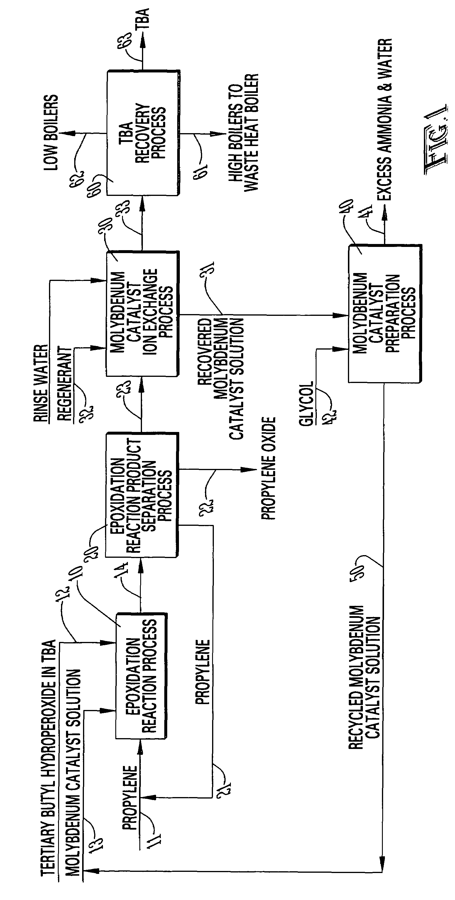
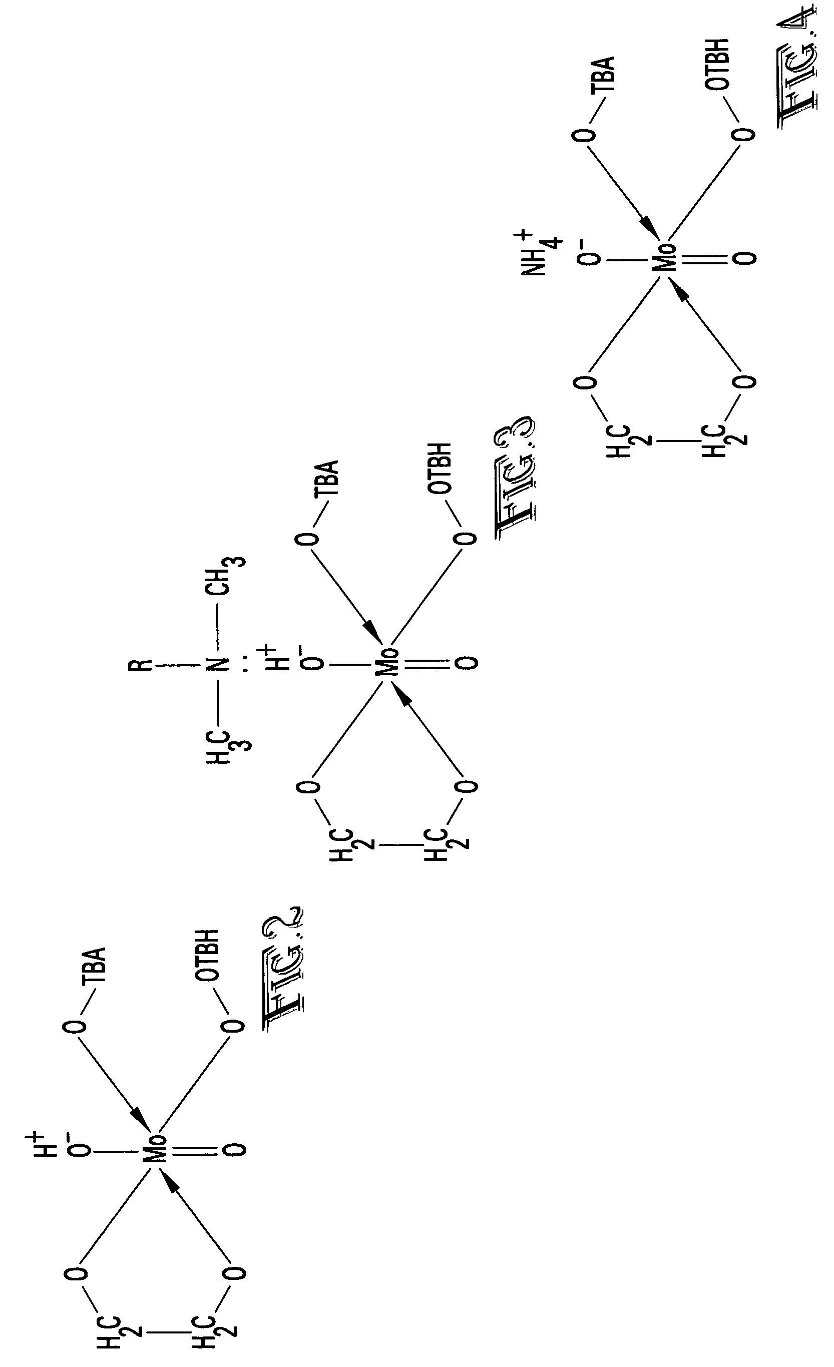
[0022]With reference to FIG. 1, the epoxidation reaction process 10 reacts a propylene stream 11 with a tertiary butyl hydroperoxide (TBH) in tertiary butyl alcohol (TBA) stream 12 in the presence of a molybdenum catalyst 13 to produce a reaction product stream 14 containing unreacted propylene, propylene oxide, TBA, unreacted TBH, molybdenum catalyst and impurities. The reaction mixture 14 is separated in an epoxidation reaction product separation process 20 to produce a recycled propylene stream 21, a propylene oxide stream 22 and and TBA process stream 23 containing TBA, the dissolved molybdenum catalyst in the active form and various impurities. The “active form” of the molybdenum is shown in FIG. 2. The molybdenum catalyst is converted into the “active form” during the epoxidation reaction.

[0023]In accordance with the present invention, the active form of the molybde...


PUM

PropertyMeasurementUnit
boilingaaaaaaaaaa
heat transfer surface foulingaaaaaaaaaa
timeaaaaaaaaaa

Abstract

A process for the recovery of molybdenum catalyst from the epoxidation reaction product of olefins with organic hydroperoxides. The active form of the glycol-molybdate epoxidation catalyst is removed from the process stream with an anion ion exchange resin. The ion exchange resin can be either a weak base or strong base type. The preferred embodiment of the invention produces a concentrated epoxidation catalyst in the “ammonium” form that is suitable for recycle to the catalyst preparation vessel. The ammonia form is converted into the active form by evaporating the water and ammonia from the recovered catalyst in the presence of a glycol. The preferred configuration of the ion exchange process is a “Lead-Lag” system. Two vessels will be in service while the third is in the regeneration mode recovering the epoxidation catalyst. A fourth polishing vessel can also be included as a “guard bed” to prevent leakage of the molybdate catalyst into the process stream. Since the ion exchange kinetics are slow compared to an aqueous system, the preferred embodiment uses a fractal fluid distribution system.

Description

CROSS-REFERENCE TO RELATED APPLICATIONS[0001]This application claims the benefit of U.S. Provisional Application No. 60 / 438,872 filed Jan. 9, 2003, which is incorporated herein by reference.STATEMENT REGARDING FEDERALLY SPONSORED RESEARCH OR DEVELOPMENT[0002]Not applicable.BACKGROUND OF THE INVENTION[0003]1. Field of the Invention[0004]The present invention relates to the recovery of molybdenum catalyst from the epoxidation reaction product of olefins with organic hydroperoxides, and in particular, to recovery of the molybdenum catalyst with an ion exchange process.[0005]2. Brief Description of the Related Art[0006]The epoxidation reaction of propylene with tertiary butyl hydroperoxide (TBH) in the presence of a catalyst produces propylene oxide and tertiary butyl alcohol (TBA). The reaction mixture from the epoxidation reaction comprises unreacted propylene, propylene oxide, TBA, unreacted TBH, the catalyst and impurities. The generic name for this reaction is the epoxidation of ol...

Claims


Application Information

Patent Timeline
Patent Type & Authority Patents(United States)
IPC IPC(8): C07D301/19
CPCC07D301/19Y02P20/141Y02P20/584
Inventor KELLY, MICHAEL D.
Owner HSBC BANK
Why Eureka
Try Eureka