Electronic vehicle toll collection system and method

a technology for electric vehicles and toll collectors, applied in traffic control systems, instruments, reradiation, etc., can solve the problems of reducing productivity, affecting highway throughput and safety, and collecting tolls by conventional means, so as to increase the rate of toll collection and enhance highway safety

Inactive Publication Date: 2007-05-29
AMTECH SYST
View PDF5 Cites 45 Cited by
  • Summary
  • Abstract
  • Description
  • Claims
  • Application Information

AI Technical Summary

Benefits of technology

[0028]Subsequently, as the vehicle approaches and passes through the first toll facility collection site, the first toll facility collection site transmits a toll-collect signal instructing the in-vehicle toll processor to debit the toll amount from its storage. The in-vehicle toll processor responds by debiting the calculated toll amount from its storage, reducing the value of the toll-money-available signal in accordance with the amount debited. Additionally, the in-vehicle toll processor transmits transaction acknowledgment signal indicating to the toll facility collection-site its identification, the calculated toll amount and the account balance.
[0032]In one aspect of the invention, the toll-facility-identifier signals, the vehicle identifier and toll-transaction signals or acknowledgment signals are encoded radio-frequency signals, and the encoding can be dynamically varied to reduce the possibility of fraud, or to carry additional selected information.

Problems solved by technology

The collection of tolls by conventional means has had a negative effect upon highway throughput and safety.
Such conditions involve a significant economic cost, through lost time, and reduced productivity.
Moreover, serious accidents at toll plazas, caused by operator or mechanical failure, have also increased in frequency.
Coin-operated toll collection systems, however, do little to increase throughput, and are susceptible to fraud, through the use of counterfeit coins.
Toll-plate systems suffer the same deficiencies, requiring each vehicle to slow sharply while entering the visual inspection area; these systems also rely heavily on toll-taker attentiveness.
This system also suffers from a number of deficiencies.
In particular, because the RFID tag lacks a machine-intelligent processor for manipulation and storage of accounts, toll authorities must maintain individual toll accounts for all users of the system.
This becomes especially burdensome in urban areas or regions of high toll traffic volume.
Toll agencies would need to manage hundreds of thousands of individual accounts, a burden that is created by operation of the AVI system.
Additionally, because the RFID tags lack a processor or user interface, vehicle operators cannot readily ascertain account balances, and have no warning as to limited or exhausted credit.
This creates both confusion, and potential safety hazards, as drivers cross over to conventional toll collection lanes with little warning.
The RFID system also raises user-privacy issues by requiring the generation and storage of detailed vehicle-specific travel records.
Although the automated toll collection system described above functions well for single lane toll roads or single lane bridges and tunnels, a significant problem can exist when the system is practiced in a multi-lane environment.
The problem of multi-pathing occurs when information transmitted from a vehicle in one lane is picked up by multiple toll lane stationary transceivers.
The effect of multi-pathing allows toll-evaders to exploit automated toll systems, as well as accidentally misallocating the debits.
The prior art systems do not provide a means for determining the actual lane position of an oncoming mobile unit.
Because of this, the prior art systems do not allow the toll system to determine the physical sequence of oncoming traffic approaching the toll system.
Moreover, the prior art systems place constraints on the size of the lanes and the spacing that must exist between each lane transceiver.

Method used


Image

  • Electronic vehicle toll collection system and method
  • Electronic vehicle toll collection system and method
  • Electronic vehicle toll collection system and method

Examples


embodiment 210

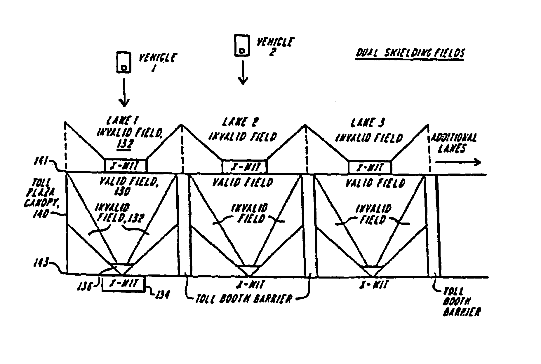
[0057]FIG. 11 shows a block diagram of a multi-lane vehicle location system 210 according to the invention. The illustrated embodiment 210 enables vehicle position to be determined and transferred from vehicle transponders, located in host vehicles 212–216, to the lane transmitter units 218–222, as the vehicles 212–216 travel along the roadway 224.

[0058]For simplicity, FIG. 11 depicts a three-lane road 224 on which the direction of travel for a given host vehicle, referred to herein as the “downstream” direction, is indicated by arrows. Those skilled in the art will appreciate that the invention can be practiced in connection with roadways having additional lanes, including multi-lane divided highways, bridges and tunnels. As one skilled in the art will appreciate the invention can also be practiced in connection with numerous other transport systems, such as railways, and waterways.

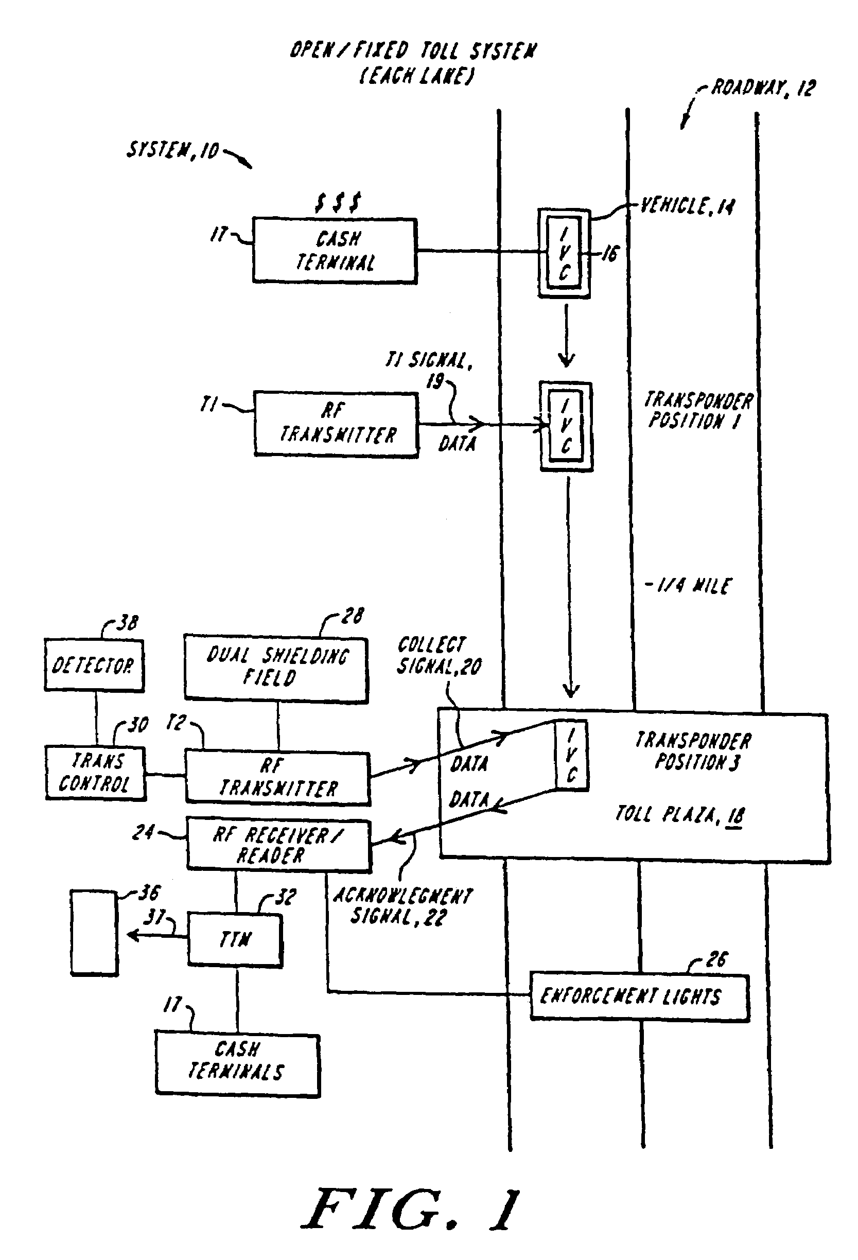
[0059]The illustrated embodiment includes two primary components; the vehicle transponders 228, and t...

first embodiment

[0237]An illustrative embodiment of this aspect of the system is implemented as follows. When the IVC is originally provided to the user, the user pays to acquire an initial balance, e.g., fifty dollars, and selects from one of several available “minimum balance” levels (e.g., twenty or thirty dollars) and also executes an authorization for billing, to a specific credit card number, telephone account, bank account or the like, any account transactions which are undertaken to maintain the minimum level. The authorization instructs the IVC to top up the account by a fixed increment, e.g., twenty dollars, when the balance drops to or below the minimum. This authorized billing information becomes part of the user's file in the central data system, while the threshold lower balance and the increment amount are entered in appropriate program instructions in the non-volatile memory 52 of the IVC. Software 53 then implements the balance check as described above against the designated thresh...


PUM


Abstract

A system for automatic collection of tolls includes an in-vehicle toll processor having memory for storing a toll-money-available quantity purchased by the user, and a toll-facility-identification site that transmits a toll-facility-identifier signal indicating the identity of the upcoming toll facility. As the vehicle approaches the identification site, the in-vehicle processor receives the identifier signal and calculates the toll to be debited. When the vehicle passes through the toll facility, the in-vehicle processor transmits its identity, its net balance and the toll, which it debits from an account balance. The in-vehicle processor may increment a low balance, in which case it transmits information which is relayed to a central system for billing. Various means for shutting down delinquent in-vehicle components or identifying offender vehicles are described.

Description

CROSS-REFERENCE TO RELATED PATENT APPLICATIONS[0001]This application is a Division of U.S. patent application Ser. No. 10 / 219,880, filed Aug. 15, 2002, now U.S. Pat. No. 7,012,547 incorporated herein by reference in its entirety, which is a continuation-in-part of U.S. patent application Ser. No. 09 / 140,778, filed Aug. 27, 1998, now U.S. Pat. No. 6,653,946, which is a continuation of U.S. patent application Ser. No. 08 / 736,270, filed Oct. 24, 1996, now U.S. Pat. No. 5,805,082, which is a continuation of U.S. patent application Ser. No. 08 / 300,424, filed Sep. 1, 1994, now abandoned, which is a continuation-in-part of U.S. patent application Ser. No. 07 / 945,534, filed Sep. 16, 1992, now U.S. Pat. No. 5,347,274 which is a continuation-in-part of U.S. patent application Ser. No. 07 / 901,277, filed Jun. 19, 1992, now U.S. Pat. No. 5,406,275, which is a continuation-in-part of U.S. patent application Ser. No. 07 / 525,103, filed May 17, 1990, now U.S. Pat. No. 5,144,553, said U.S. patent app...

Claims


Application Information

Patent Timeline
Patent Type & Authority Patents(United States)
IPC IPC(8): G08G1/065
CPCG07B15/063G08G1/017
Inventor HASSETT, JOHN J.
Owner AMTECH SYST
Why Eureka
Try Eureka