MEMS-based optical communications beam steering apparatus

a beam steering and optical communication technology, applied in the field of optical communication, can solve the problems of long-distance free space optical communication, unwieldy, lack of speed, precision, reliability, etc., and achieve the effect of maximum signal strength

Inactive Publication Date: 2007-05-29
SPACE PHOTONICS
View PDF17 Cites 5 Cited by
  • Summary
  • Abstract
  • Description
  • Claims
  • Application Information

AI Technical Summary

Benefits of technology

[0011]The present invention is directed to a MEMS-based device to provide angular adjustment to an optical fiber situated in the focal plane of an optical beam pointing and tracking system. The MEMS device employs surface micro-machined actuators to move an optical fiber through the optical plane of an optical signal receiver or transmitter. The fiber is fed through a bore in the MEMS device, which allows the actuators to manipulate the optical fiber in the X-Y plane of the receiver or transmitter. In the case of a receiver, this movement allows for signal tracking in order that the maximum signal strength may be received. In the case of a transmitter, this allows the signal to be pointed in precisely the desired direction. The MEMS device may be manipulated by various electrical signals that drive the actuators. A yoke may be employed to link the actuators with the optical fiber. By moving the optical fiber within the focal plane of a receiver or transmitter, signals may be received or sent, respectively, along a precisely defined direction.
[0012]By use of this MEMS-based device for beam steering, no gimbals are required in the pointing and tracking system, thereby greatly reducing the size, weight, and power consumption of the pointing and tracking system. In addition, the MEMS-device may improve performance by providing faster response times to a signal to change the direction of a receiver or transmitter. The result is a laser communications system that is more practical for low-cost, high-bandwidth application markets. Such a system is also capable of providing the high performance necessary for mission-critical applications such as military avionics and space-based inter-satellite communications, without decreasing reliability or functionality. In fact, reliability may improve over the complex mechanical systems required when gimbals are employed, since MEMS devices are typically more reliable than such systems.
[0013]It is therefore an object of the present invention to provide for a MEMS-based device for optical beam steering that achieves high speed and angular precision without the use of gimbals.
[0015]It is also an object of the present invention to provide for a MEMS-based device for optical beam steering that is of a relatively small size and weight.
[0016]It is also an object of the present invention to provide for a MEMS-based device for optical beam steering that has a relatively low production cost.
[0017]It is also an object of the present invention to provide for a MEMS-based device for optical beam steering that has a decreased response time to a re-directed signal, thereby allowing faster acquisition and tracking of a signal source.

Problems solved by technology

These types of systems, however, have generally proven to be unwieldy, or lack the speed, precision, and reliability necessary for high-speed, long-distance free-space optical communications.
Gimballed beam-steering systems do, however, suffer from several important disadvantages.
Such systems are quite heavy due to the weight of the mechanical components, motors, and servos necessary for such a system.
Gimballing systems are also quite bulky due to the required mechanical components, which is also a significant disadvantage in the design of airborne and spaceborne systems.
Finally, mechanical gimballing systems require the use of a great deal of electrical power, far more power than is typically consumed by the electronics associated with an optical receiver or transmitter system.

Method used


Image

  • MEMS-based optical communications beam steering apparatus
  • MEMS-based optical communications beam steering apparatus
  • MEMS-based optical communications beam steering apparatus

Examples


Embodiment Construction

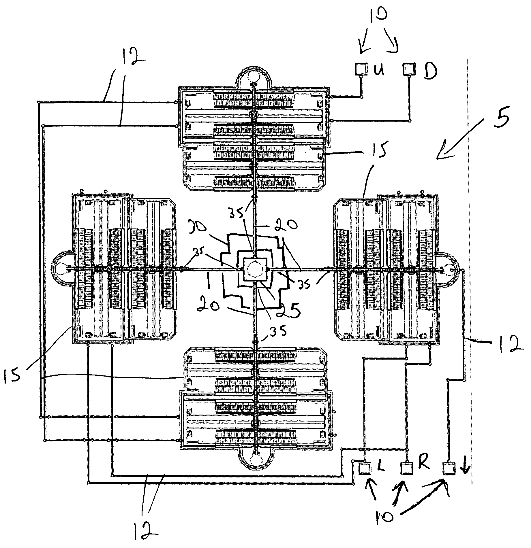
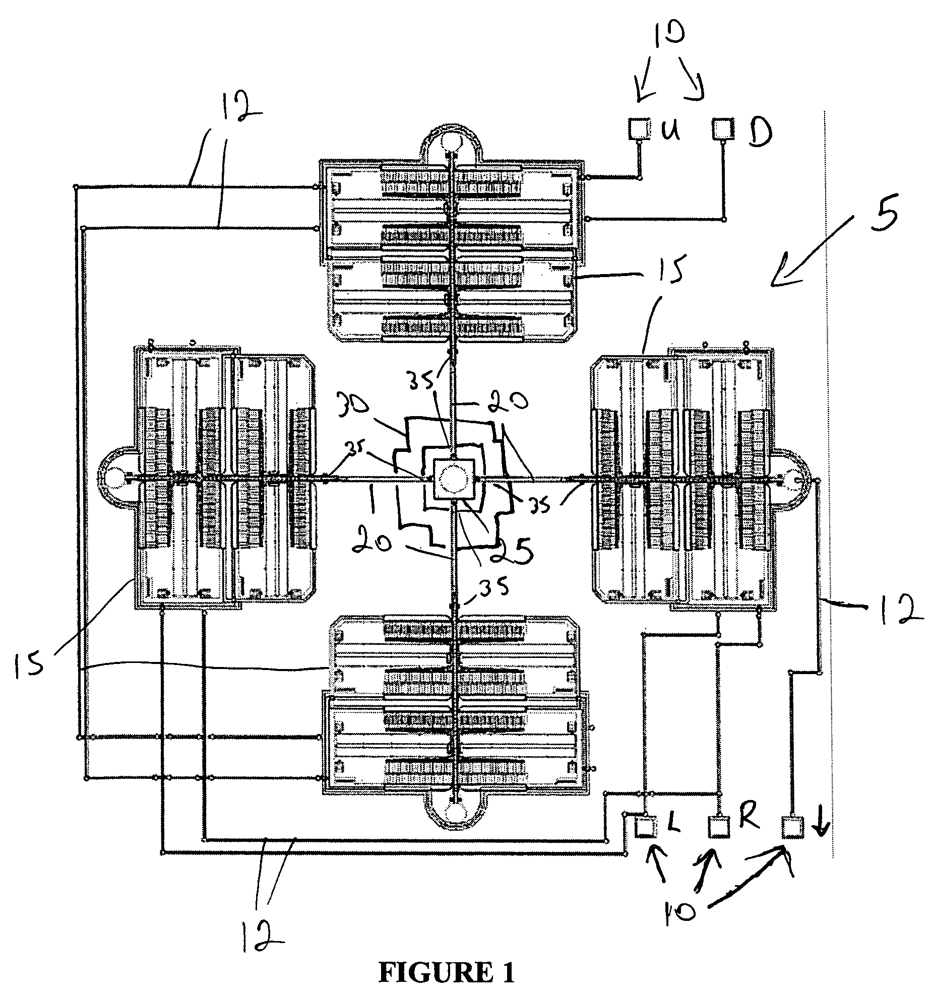
[0024]With reference to FIG. 1, the preferred embodiment of the present invention may be described. MEMS device 5 is constructed using IC / MEMS fabrication techniques, preferably successive selective deposition and etching using ultraviolet (UV) photolithography on a single crystal silicon wafer. Electrical signals propagated into device 5 enter through one of bond pads 10. Each bond pad 10 is connected by wirebonding to electrical conductive paths 12. Bond pads 10 and conductive paths 12 may be constructed of metal, highly doped polysilicon, or other conductive materials. Conductive paths 12 are, in turn, electrically connected to electrostatic comb-drive actuators 15. As a result of this arrangement, a signal voltage applied at a bond pad 10 is propagated to one or more electrostatic comb-drive actuators 15.

[0025]In the preferred embodiment, device 5 comprises four electrostatic comb-drive actuators 15. Comb-drive actuators operate on the principle of electrostatic repulsion betwee...


PUM


Abstract

A MEMS-based optical steering apparatus for free space optical transmitters, receivers, and transceivers is disclosed. The MEMS device comprises actuators linked to an optic fiber, the actuators operable to maneuver the optical fiber in the X-Y plane at the focal point of the transmitter, receiver, or transceiver. The MEMS device may thus be used to replace gimbals for beam steering applications.

Description

CROSS-REFERENCE TO RELATED APPLICATIONS[0001]This application claims the benefit of U.S. provisional patent application No. 60 / 609,420, entitled “MEMS-Based Optical Communications Beam Steering Apparatus” and filed on Sep. 13, 2004, and U.S. provisional patent application No. 60 / 609,413, entitled “Apparatus and Method for Free Space Optical Communications Beam Steering without Gimbals” and also filed on Sep. 13, 2004. The entire disclosures of these applications are incorporated herein by reference.STATEMENT REGARDING FEDERALLY SPONSORED RESEARCH OR DEVELOPMENT[0002]The U.S. Government has a paid-up license in this invention and the right in limited circumstances to require the patent owner to license others on reasonable terms as provided for by the terms of contract no. F29601-02-C-0021 awarded by the United States Air Force Research Laboratory.BACKGROUND OF THE INVENTION[0003]The present invention relates to the field of optical communications, and in particular to the field of b...

Claims


Application Information

Patent Timeline
Patent Type & Authority Patents(United States)
IPC IPC(8): G02B26/00
CPCG02B26/0841
Inventor CHALFANT, III, CHUCK H.ORLANDO, FRED J.GREGORY, JEFFREY T.O'NEAL, CHAD B.
Owner SPACE PHOTONICS
Why Eureka
Try Eureka