Spraying method and apparatus

a technology of spraying and nozzle, which is applied in the direction of mechanical equipment, combustion-air/fuel-air treatment, machines/engines, etc., can solve the problems of increasing water consumption, increasing combustion temperature, and additional waste, and achieves good and efficient humidification of intake air, reduces the volume of the turbocharger, and increases the efficiency of the turbocharger

Inactive Publication Date: 2007-06-05
MARIOFF CORP OY
View PDF13 Cites 42 Cited by
  • Summary
  • Abstract
  • Description
  • Claims
  • Application Information

AI Technical Summary

Benefits of technology

[0011]The solution of the invention has numerous significant advantages. The apparatus is connected directly to the structures of the air intake duct and it produces a fine mist directly without using any extra chambers or other containers, it is able to make full use of the heat quantity required for the vaporization of the water, cooling the intake air at each spray injection point to a temperature close to the wet bulb temperature (or adiabatic saturation temperature, which in the case of a water-air mixture is practically the same thing), i.e. to the temperature to which the air temperature can be reduced by vaporization of water. As connecting the apparatus of the invention to a turbocharged engine does not involve any changes in the cubic volume of the air intake system, it has no adverse effect on the power output of the engine, either.
[0012]By the method of the invention, very good and efficient humidification of intake air is achieved. The heating of intake air used in the method can be implemented using a relatively economic construction as it does not have to withstand the high pressure after the turbocharger. The efficiency of the turbocharger is increased because the mass flow passing through it is larger than before. In addition, the engine's response time for power boost is accelerated because the turbocharger duct volume is reduced.
[0013]Another advantage of the apparatus of the invention is that the humidity of the intake air can be increased stepwise after each heat supply point, yet before the last heat supply point, which can be used as a water evaporation surface, thus controlling the humidity of the gas fed into the cylinder and therefore the formation of nitrogen oxides within desired limits.BRIEF DESCRIPTION OF THE DRAWINGS

Problems solved by technology

When the water is supplied in the form of droplets together with the intake air, some of it is additionally wasted during the scavenging period and water consumption is increased.
The effect of reducing the combustion temperatures increases with the water vapor concentration, yet without producing an undesirable effect on efficiency.
A drawback with this apparatus is that the device mounted between the turbocharger and the cylinder increases the cubic volume of the air intake ductwork, which has a considerable effect on the power output of the engine.
Another drawback with the apparatus is that the heated water used for vaporization and flushed over the evaporation surfaces has the effect of increasing the temperature of the air.
The device is unable to make use of the cooling effect produced in connection with the vaporization of the water, but the gas output from the device is at a relatively high temperature, so the amount of water vapor required for the reduction of nitrogen oxides and therefore also the water consumption are increased considerably.
A drawback with this system is the relatively low temperature of the supply air, which is why the amount of water vapor evaporated into the air remains small, and thus no significant nitrogen oxide reducing effect is achieved.
Another drawback is that when the amount of water is increased, the water droplets can evaporate after the air has reached a saturated state, with the result that the water droplets drift into the turbocharger and cause wear of the turbocharger vanes through droplet erosion.
In practice, however, a turbocharger rotating at a very high speed—about 50,000–100,000 rpm—has proved to be very sensitive to droplet erosion as referred to above.

Method used


Image

  • Spraying method and apparatus
  • Spraying method and apparatus

Examples


Embodiment Construction

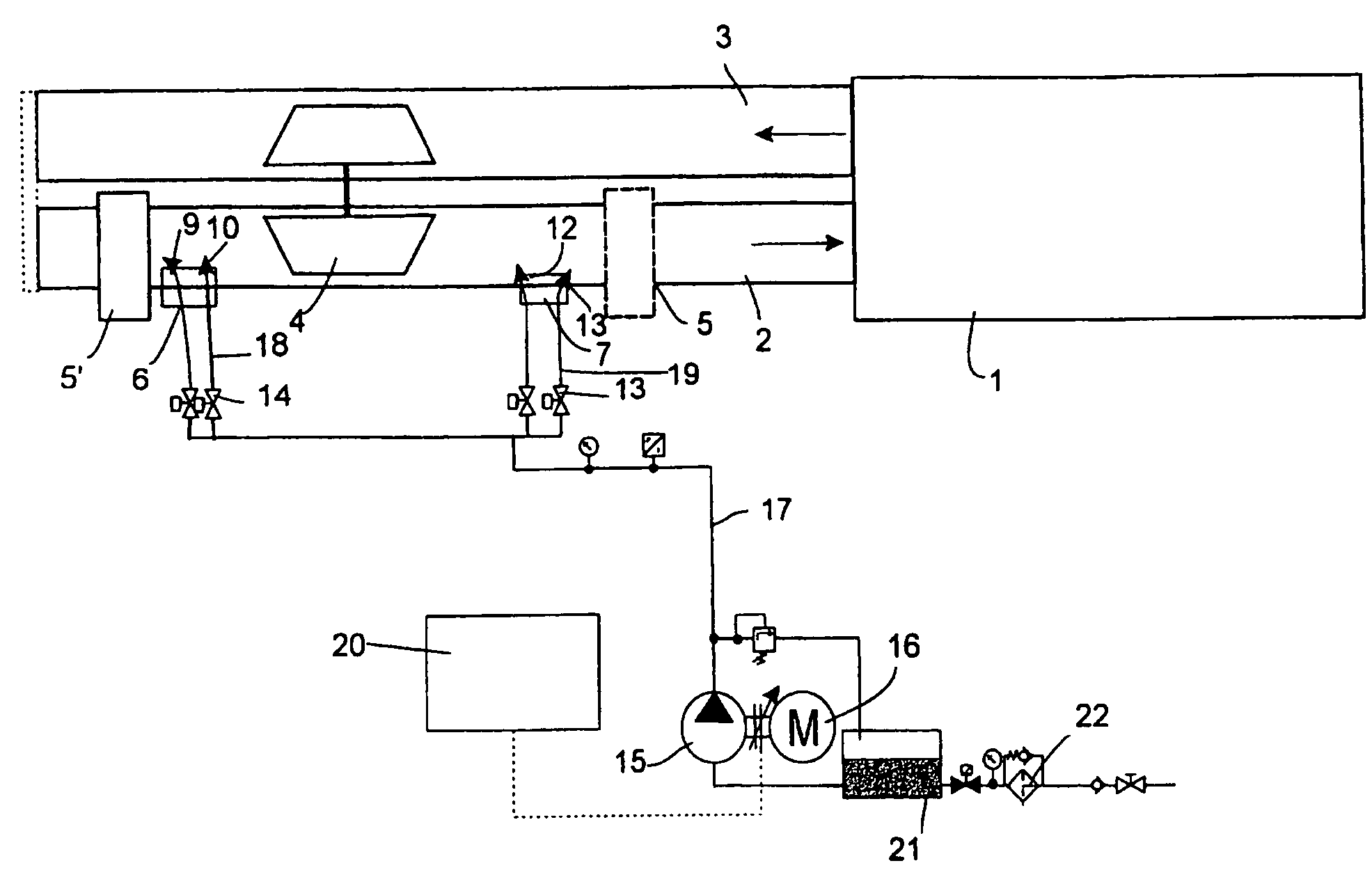
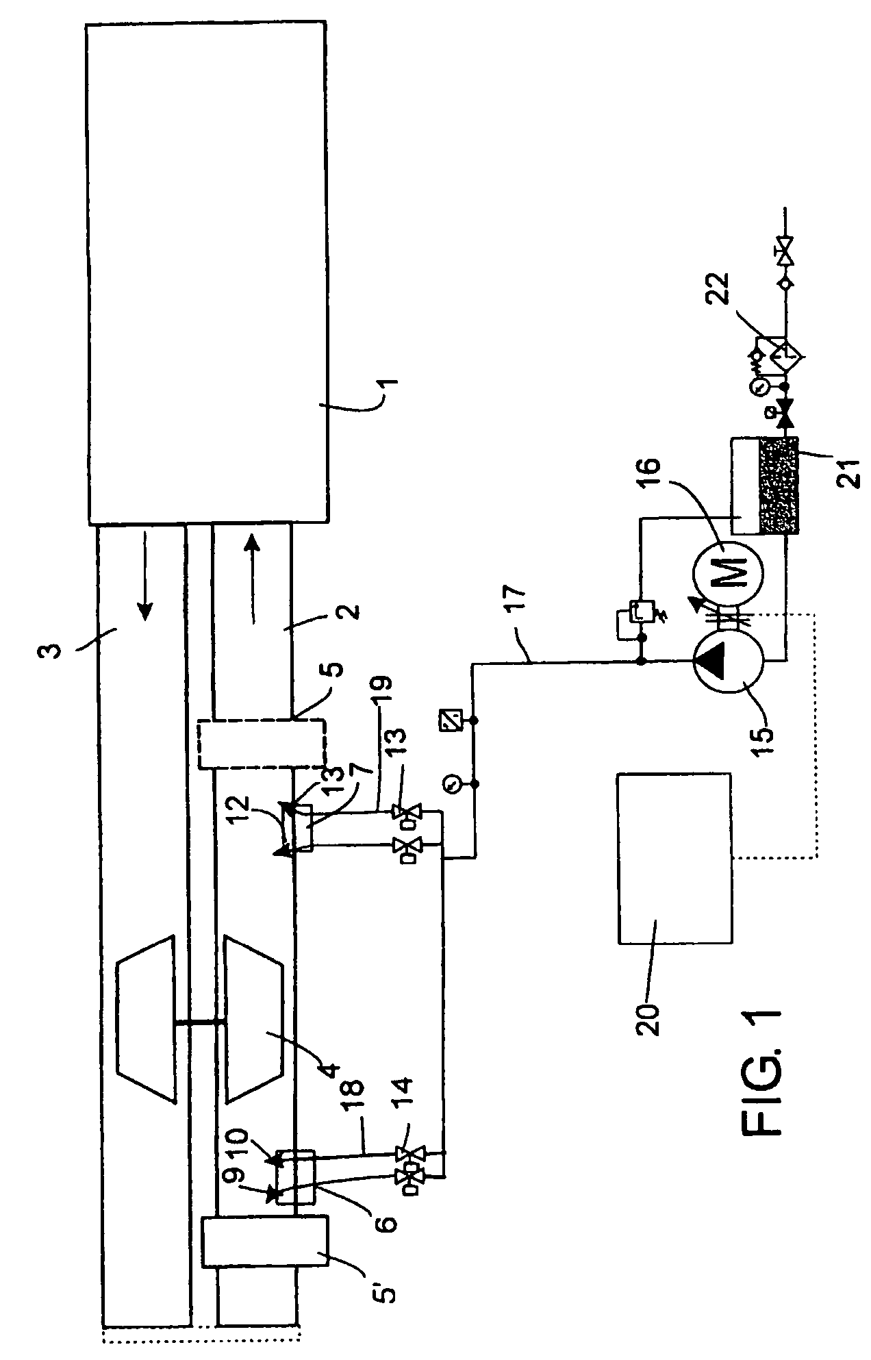
[0016]FIG. 1 is a diagrammatic representation of a apparatus according to the invention, installed in connection with the air intake duct 2 of a piston engine, such as a diesel engine. The air intake duct 2 and the exhaust gas duct 3 are shown in a simplified form in the FIGURE. The engine presented in the FIGURE is provided with a turbocharger 4, which feeds air under positive pressure into the air intake ductwork 2 of the engine. To reduce the nitrogen oxide emissions of the engine, the air intake ductwork is provided with at least one spraying head 6, 7 fitted to supply water mist into the intake ductwork 2. Turbocharged engines are traditionally provided with a charge-air intercooler 5, which in the FIGURE is depicted in broken lines.

[0017]According to the invention, the intake air is heated by means of a heat exchanger element 5′, such as an intake air intercooler relocated to the appropriate position and converted to function as a heater as well, e.g. by providing it with equi...


PUM


Abstract

A method for spraying an aqueous liquid into the air intake duct (2) of a turbocharged piston engine (1) for humidifying the intake air to reduce nitrogen oxide emissions. In a first stage in the method, the intake air is heated by a heat exchanger element (5′) before the turbocharger and water mist is injected into the air intake duct after the first heading stage through at lea one first nozzle (9, 10), and in a second stage the intake air is compressed by the turbocharger (4), causing its temperature to rise, and water mist is injected into the air intake duct through at least one second nozzle (12, 13) after the second stage.

Description

BACKGROUND OF THE INVENTION[0001]The present invention relates to a method as defined in the preamble of claim 1 for spraying an aqueous liquid into the air intake duct of a turbocharged piston engine for humidifying the intake air to reduce nitrogen oxide emissions.[0002]The invention also relates to a spraying apparatus as defined in claim 3 for humidifying the intake air of a turbocharged piston engine to reduce nitrogen oxide emissions, said apparatus comprising at least one nozzle for spraying an aqueous liquid into the air intake duct.[0003]The invention thus concerns especially a method and apparatus for supplying water into the intake air of a turbocharged piston engine to reduce nitrogen oxide emissions (NOx). At the high combustion temperatures, the combustion process in the cylinder of a piston engine produces nitrogen oxides, which are emitted together with the exhaust gases into the atmosphere. Because of the harmful climatic effects of nitrogen oxide emissions, efforts...

Claims


Application Information

Patent Timeline
Patent Type & Authority Patents(United States)
IPC IPC(8): F02B47/02F02B3/06F02B29/04F02M25/028F02M31/04
CPCF02B29/0406F02B47/02F02M31/042F02M25/028F02M25/0225F02M25/0227F02B3/06Y02T10/146Y02T10/126Y02T10/121Y02T10/12
Inventor MAHLANEN, TIMO
Owner MARIOFF CORP OY
Why Eureka
Try Eureka