Hole-assisted single mode optical fiber

a single-mode optical fiber and optical fiber technology, applied in the field of single-mode optical fibers, can solve the problems of reducing the optical confinement of light propagating through the optical fiber within the optical core, reducing the refractive index profile in the radial direction, and reducing the bending loss resistance of the optical fiber. , to achieve the effect of reducing the cost of manufacturing and high bending loss resistan

Active Publication Date: 2007-06-05
NIPPON TELEGRAPH & TELEPHONE CORP
View PDF24 Cites 50 Cited by
  • Summary
  • Abstract
  • Description
  • Claims
  • Application Information

AI Technical Summary

Benefits of technology

[0015]According to the present invention, it becomes possible to satisfy all the characteristics of the bending loss equal to or less than 1 dB / m at the bending radius 10 mm, and the effective cross-sectional area Aeff equal to or greater than 150 μm2 in a region in which the theoretical cutoff wavelength in the higher-order LP11 mode is equal to or less than 1500 nm and the operating wavelength is from 1260 nm to 1625 nm, for example, by providing, in addition to the core region and first cladding region having the same refractive index gradient as that of a conventional single mode fiber, the second cladding region having at least four air hole regions within the first cladding region, and by optimizing the core radius r1, the relative index difference A of the core region, the air hole radius r2, and the distance d of the air hole regions, thereby offering a marked advantage of being able to implement the reduction in the optical nonlinearity in a wide single mode operation region.
[0016]In addition, according to the present invention, it also becomes possible for the single mode fiber with the same structure as described above to satisfy the theoretical cutoff wavelength in the higher-order LP11 mode equal to or less than 1500 nm and the bending loss equal to or less than 1 dB / m at the bending radius 10 mm in the operating wavelength region from 1260 nm to 1625 nm, and to implement high bending loss resistance, to keep the MFD characteristics equivalent to that of the conventional SMF at the wavelength 1310 nm, and to make the variations in the MFD with reference to the conventional SMF equal to or less than ±10% even at the wavelength 1625 nm, thereby offering an advantage of being able to achieve good connection characteristics with the conventional SMF.
[0017]Furthermore, since the single mode fiber in accordance with the present invention has a structure that provides many air hole regions to a single mode fiber with a prescribed refractive index profile, it can be fabricated comparatively easier.

Problems solved by technology

Long-distance and large-capacity optical communication using optical amplification technique has a problem of degradation in transmission characteristics due to optical nonlinear phenomena in single mode fibers.
The increase in the effective cross-sectional area Aeff in the design and optimization of the refractive index profile, however, will generally complicate the refractive index profile in the radial direction in a cross section of a single mode fiber (SMF).
In addition, in the SMF whose effective cross-sectional area Aeff is increased, the optical confinement of the light propagating through the optical fiber within the optical core reduces, and the bending loss characteristic is deteriorated.
This offers a problem in that the actual value of the feasible effective cross-sectional area Aeff is limited to a region in which the acceptable bending loss characteristic is achieved.
This presents a problem in that the effective operating wavelength region is limited to a longer wavelength region of 1400 nm or more, for example (refer to Japanese Patent Application Laid-open No. 2001-147338 (Claim 13 and paragraph , for example).
Furthermore, although the conventional SMF has a simple structure and comparatively large effective cross-sectional area Aeff, its adaptive or applicable area is limited to a region in which the bending radius is comparatively large such as from 20 mm to 30 mm because of the degradation in the bending loss characteristics.
Accordingly, it has a drawback of being unable to make compact in actual optical transmission paths or optical wiring because the wiring or storage space is limited in accordance with the acceptable bending radius.
However, the SMFs of this type have a problem of impairing the handling characteristics such as the splice loss as a result of the reduction in the MFD.

Method used


Image

  • Hole-assisted single mode optical fiber
  • Hole-assisted single mode optical fiber
  • Hole-assisted single mode optical fiber

Examples


first embodiment

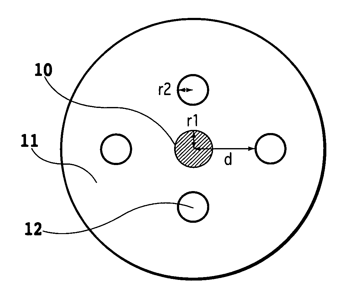
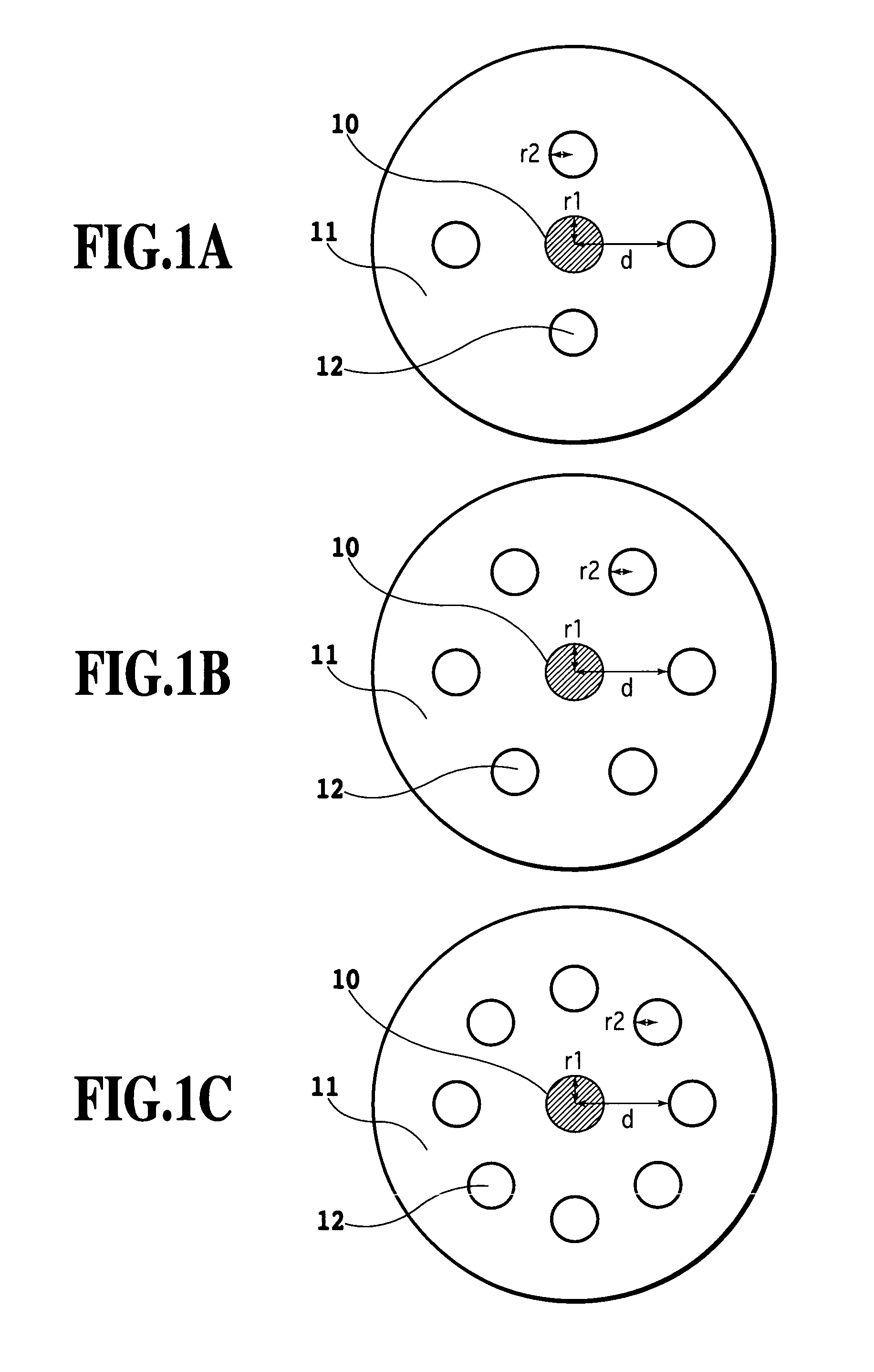
[0029]FIGS. 1A–1C are schematic cross-sectional views each showing a cross-sectional structure of an embodiment of a hole-assisted single mode optical fiber in accordance with the present invention: FIG. 1A shows an example with four air holes; FIG. 1B shows an example with six air holes; and FIG. 1C shows an example with eight air holes.

[0030]The single mode fiber in accordance with the present invention comprises a core region 10 with a radius r1, a first cladding region 11 that surrounds the core region and has a uniform refractive index, and a second cladding region including at least four air hole regions 12 that are placed at a distance d from the center of the core region 10 and have a radius r2. It is assumed that the air hole regions 12 are each formed in the longitudinal direction of the optical fiber, and are disposed separately at fixed same interval in a cross section of the optical fiber, and that their diameters are substantially constant in average throughout the lon...

second embodiment

[0045]Next, as the second embodiment in accordance with the present invention, an example will be described in which the effective cross-sectional area Aeff is increased by optimizing the relative index difference Δ of the core region 10 and the core radius.

[0046]FIG. 8 is a diagram illustrating relationships between the relative index difference Δ of the core region 10 from the refractive index of the first cladding region 11 and the effective core radius A, in which the bending loss at the bending radius 10 mm is equal to or less than 1 dB / m. Here, the effective core radius A is defined as the distance from the center of the core region 10 to the extreme circumference of the second cladding region, which is equal to A=d+2×r2 (see, FIGS. 1A–1C). As an example, the number of the air hole regions 12 constituting the second cladding region is six, the air hole radius r2 is 0.3 times the core radius r1, and the air hole distance d is three times the core radius r1.

[0047]FIG. 8 shows th...


PUM


Abstract

A single mode fiber is provided which is suitable for high-speed, large-capacity optical communication and for optical wiring. The single mode fiber has a first cladding region with a uniform refractive index, a core region with a refractive index higher than that of the first cladding region, and a second cladding region including at least four air hole regions placed in the first cladding region. Optimization can be achieved by making the distance from the center of the core region to the air hole regions equal to 2–4.5 times the core radius, and the air hole radius equal to or greater than 0.2 times the core radius. It is preferable the core radius be 3.7–4.8 μm, the relative index difference of the core region from the first cladding region be 0.3–0.55 %.

Description

TECHNICAL FIELD[0001]The present invention relates to a single mode fiber suitable for high-speed, large-capacity optical communication and optical wiring, and particularly to a hole-assisted single mode optical fiber.BACKGROUND ART[0002]Long-distance and large-capacity optical communication using optical amplification technique has a problem of degradation in transmission characteristics due to optical nonlinear phenomena in single mode fibers.[0003]The optical nonlinearity in a single mode fiber varies in proportion to a nonlinear coefficient n2 / Aeff obtained by dividing a nonlinear refractive index n2 by an effective cross-sectional area Aeff (G. P. Agrawal, “Nonlinear Fiber Optics (second edition)”, Academic Press, 1995, particularly refer to section 2.3.1, p. 42). Accordingly, the degradation in the transmission characteristics due to the optical nonlinear phenomena in the long-distance and large-capacity optical communication can be reduced by decreasing the nonlinear coeffici...

Claims


Application Information

Patent Timeline
Patent Type & Authority Patents(United States)
IPC IPC(8): G02B6/032G02B6/02
CPCG02B6/02019G02B6/02333G02B6/02366G02B6/0365
Inventor NAKAJIMA, KAZUHIDETAJIMA, KATSUSUKEZHOU, JIANSANKAWA, IZUMIHOGARI, KAZUO
Owner NIPPON TELEGRAPH & TELEPHONE CORP
Why Eureka
Try Eureka