Method for controlling the position of a permanent magnetically supported rotating component

a technology of rotating components and magnetic supports, which is applied in the direction of prosthesis, electronic commutator, therapy, etc., can solve the problems of corresponding disadvantages for patients, and achieve the effects of increasing the magnetic field, low dissipation, and producing heat energy

Inactive Publication Date: 2007-06-12
BERLIN HEART GMBH
View PDF43 Cites 67 Cited by
  • Summary
  • Abstract
  • Description
  • Claims
  • Application Information

AI Technical Summary

Benefits of technology

[0004]Such a fluid pump can be integrated in the known way in a synchronous motor without brushes. The fluid pump consists according to WO 00/640 30 essentially of a cylindrical tube, which can be connected at both sides to a fluid system. The tube is surrounded by the stator, consisting of the metal packet, the winding and the iron flux return hood. The rotor comprises permanent magnetic field exciters and has on its outer cover delivery devices for the fluid, so that the fluid can be axially delivered in the annular space between the tube and the rotor.
[0005]The rotor is magnetically supported. It carries for the purpose on its both end sides cylindrical or annular permanent magnets attached thereon, which are magnetised in the axial direction. The permanent magnets of the rotor are opposed by counter magnetised permanent magnets, which e.g. can be arranged in the end sides of guiding devices, which themselves are mounted in the cylindrical tube.
[0006]Both magnet pairs act stabilisingly in radial direction, when they are orientated to attract each other, i.e., the radial support is passively stable. The rotor is, however, instable in the axial direction.
[0007]Without additional stabilisation the rotor would be attracted by one of the two pairs of permanent magnets. Therefore, control coils are arranged on the stator sides in such a way, tha

Problems solved by technology

The blood is subjected, then, easily to the haemolysis or the formation o

Method used


Image

  • Method for controlling the position of a permanent magnetically supported rotating component
  • Method for controlling the position of a permanent magnetically supported rotating component
  • Method for controlling the position of a permanent magnetically supported rotating component

Examples


Embodiment Construction

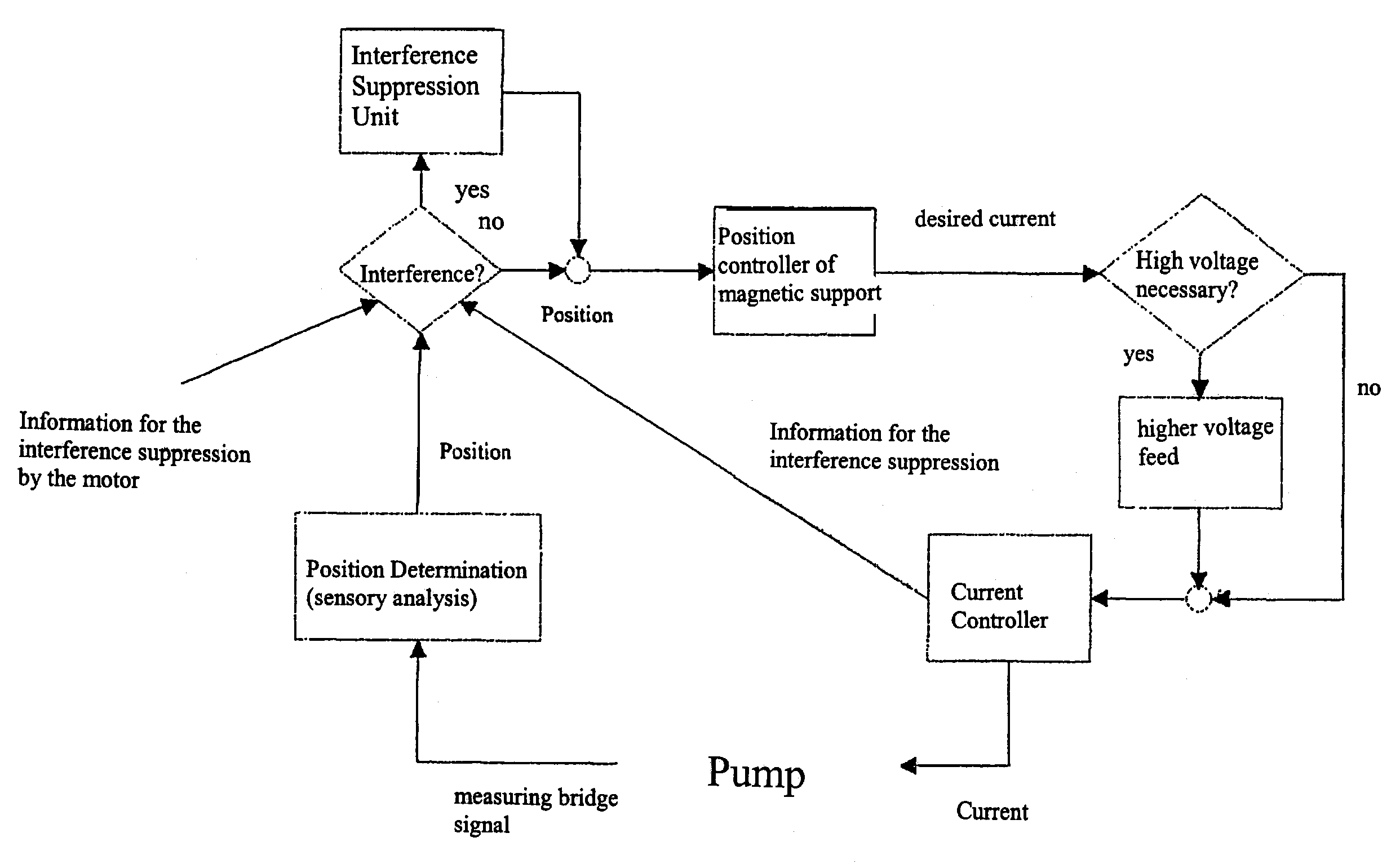
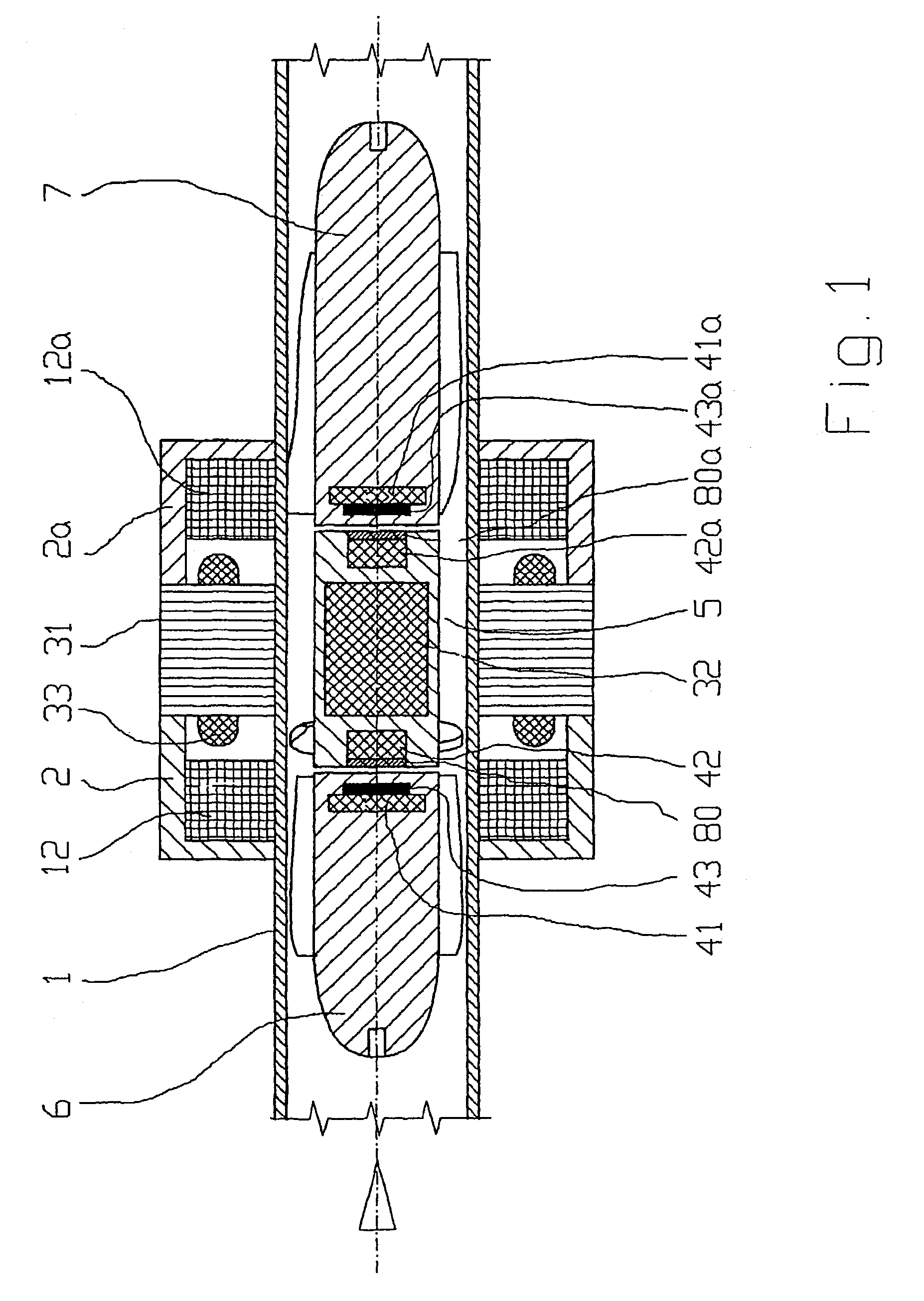
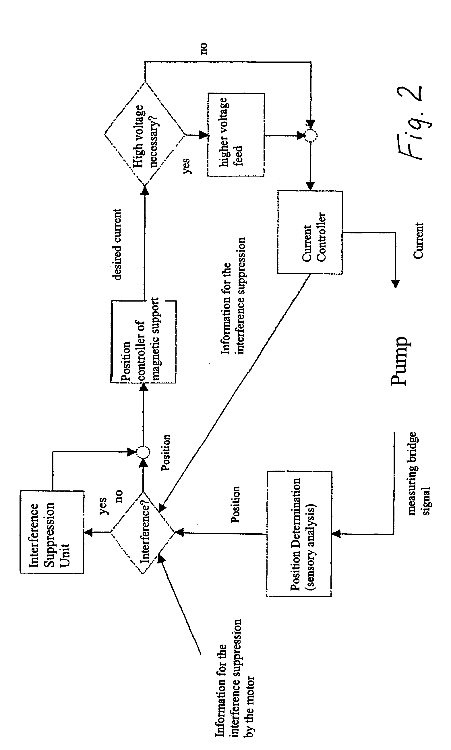
[0022]FIG. 1 shows such an axial pump suitable for the execution of the method. The drive of the blood pump works according to the principal of an electronic commutated synchronous motor. The motor has a stator, consisting of a metal sheet packet 31, of windings 33 and iron flux return hoods 2, 2a and a rotor 5 with a permanent magnetic core 32. The stator encloses a tubular hollow body 1, in which in axial direction a fluid, in the present case blood, is delivered. The rotor 5 is supported magnetically free of contact.

[0023]The magnetical support (bearing) consists of permanent magnets 42, 42a on the rotor end sides and permanent magnets 41, 41a on the end sides of the guiding devices 6 and 7. The guiding devices 6, 7 are mounted on the inner wall of the tubular hollow body 1.

[0024]To the magnetic support (bearing) further belong control coils 12, 12a. Sensor coils 43, 43a in the guiding devices 6, 7 and short circuit rings 80, 80a arranged opposed thereto, serve for measuring the ...


PUM


Abstract

Since disruptive forces can be continuously exerted upon a rotor during a pulsatile flow through a pump with a magnetically mounted rotor (permanent magnets and addition control current coils), it is necessary to adjust position i.e. modify axial rotor position very quickly. The control current should only result in small amounts of losses. According to the invention, the current is pulse-width modulated by the control current coils by means of a set value predetermined by a controller which is arranged downstream from a position sensing system. If the set value is high, it is switched to a higher voltage level and the real value of the position sensing system is stored for a defined period of time, respectively beginning with the switching flank of the control current, and the position sensing system is disconnected during said period of time.

Description

BACKGROUND OF THE INVENTION[0001]The invention relates to a method for controlling the position of a permanent magnetically supported rotating component, e.g. of the rotor of a synchronous motor without brushes, by means of a position determination of this component by means of a position sensory analysis and additional control current coils, influencing the magnetic field of the permanent magnetic support and which current value is determined by the position of the component. The synchronous motor can for example serve as a drive for an axial fluid delivery pump.[0002]Multiphase fluids, e.g. emulsions and dispersions with a low stability can easily reach into instable areas during the delivery in corresponding delivery systems.[0003]An especially sensitive fluid is blood. Blood is hermetically shielded in the natural recirculation system from the environment, so that no foreign interferences are acting upon it. If, however, the necessity exists, to substitute the heart by an artifi...

Claims


Application Information

Patent Timeline
IPC IPC(8): A61M1/12F04D3/00F04D29/046F04D13/02F04D13/06F04D29/04F04D29/048F16C32/04F16C39/06H02K5/128H02K7/09H02K7/14H02P6/18
CPCF04D3/00F04D13/0606F04D29/041F04D29/048F16C32/0457F16C32/0478H02K7/09H02K7/14F16C32/047F16C2316/18H02K5/128F16C2360/44F04D13/0646A61M60/82A61M60/422A61M60/148A61M60/237A61M60/178
Inventor HOFFMANN, JANARNDT, ANDREASMERKEL, TOBIAS
Owner BERLIN HEART GMBH
Why Eureka
Try Eureka