Pyrene derivative, light emitting element, and light emitting device
a technology of light emitting element and derivative, which is applied in the direction of discharge tube luminescence screen, other domestic articles, natural mineral layered products, etc., can solve the problems of insufficient luminous efficiency, difficult to keep the film morphologically uniform, and difficult to obtain stable light emission for a long stretch of time, so as to achieve efficient stable light emission and high-efficiency luminescence
- Summary
- Abstract
- Description
- Claims
- Application Information
AI Technical Summary
Benefits of technology
Problems solved by technology
Method used
Image
Examples
embodiment 1
(Embodiment 1)
[0027]A pyrene derivative according to the present invention has a structure represented by the above-mentioned general formula (1). Specific examples of R1 to R4 include alkyl groups such as a methyl group, an ethyl group, an isopropyl group, and a cyclohexyl group, alkoxyl groups such as a methoxy group, an isopropoxy group, and a hexyloxy group, aryl groups such as a phenyl group, a naphthyl group, and an anthryl group, diarylamino groups such as a diphenylamino group and a carbazolyl group, and a silyl group having one or more alkyl groups or one or more aryl groups.
[0028]In addition, by appropriately changing the structures of R1 to R4 in the general formula (1), pyrene derivatives represented by the following structure formulas (2) to (12) can be formed, for example. However, the present invention is not to be considered limited to these.
[0029]
[0030]The pyrene derivative according to the present invention is large in molecular weight and has a three-dimensional s...
embodiment 2
(Embodiment 2)
[0034]In the present embodiment, a light-emitting element using the pyrene derivative shown in Embodiment 1 will be described.
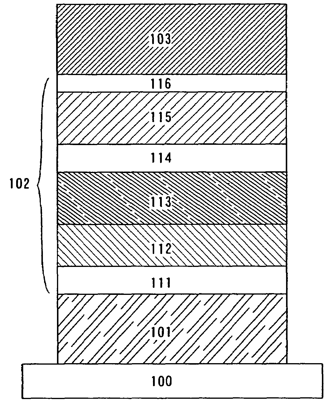
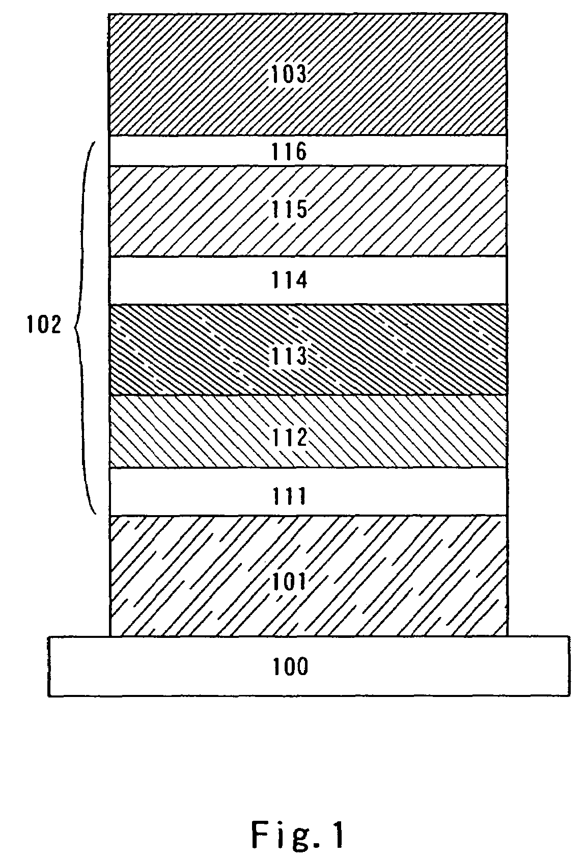
[0035]The structure of the light-emitting element according to the present invention is not particularly limited, which can be selected appropriately for any purpose. Basically, the structure has a layer including a luminescent material between a pair of electrodes (an anode and a cathode), which is formed by appropriately combining layers such as a hole injecting layer, a hole transporting layer, a light-emitting layer, a hole blocking layer, an electron transporting layer, and an electron injecting layer. For example, a light-emitting element that has a structure such as an anode / a hole injecting layer / a light-emitting layer / an electron transporting layer / a cathode, an anode / a hole injecting layer / a hole transporting layer / a light-emitting layer / an electron transporting layer / a cathode, an anode / a hole injecting layer / a hole transporting layer...
embodiment 3
(Embodiment 3)
[0053]In the present embodiment, a light-emitting device according to the present invention will be described.
[0054]In the present embodiment, the light-emitting element using the pyrene derivative according to the present invention, which is shown in Embodiment 2, is manufactured over a substrate including a material such as glass, quartz, or transparent plastic. By manufacturing a plurality of light-emitting elements using the pyrene derivative according to the present invention over a substrate, a passive matrix light-emitting device can be manufactured.
[0055]In addition, other than the substrate including the material such as glass, quartz, or transparent plastic, for example, as shown in FIG. 5, a light-emitting element in contact with a thin film transistor (TFT) array may be manufactured, and in this case, an active matrix light-emitting device where driving of a TFT is controlled by a TFT can be manufactured. In FIG. 5, a TFT 11 and a TFT 12 are formed over a s...
PUM
| Property | Measurement | Unit |
|---|---|---|
| work function | aaaaa | aaaaa |
| work function | aaaaa | aaaaa |
| thickness | aaaaa | aaaaa |
Abstract
Description
Claims
Application Information
 - R&D
- Intellectual Property
- Life Sciences
- Materials
- Tech Scout
- Unparalleled Data Quality
- Higher Quality Content
- 60% Fewer Hallucinations
Browse by: Latest US Patents, China's latest patents, Technical Efficacy Thesaurus, Application Domain, Technology Topic, Popular Technical Reports.
© 2025 PatSnap. All rights reserved.Legal|Privacy policy|Modern Slavery Act Transparency Statement|Sitemap|About US| Contact US: help@patsnap.com


