
Hybrid power system including an engine and a fuel cell module

a power system and fuel cell technology, applied in the direction of gaseous engine fuel, plural diverse prime-mover propulsion mounting, gas pressure propulsion mounting, etc., can solve the problems of reducing the power generation efficiency of the fuel cell, unable to carry out refueling in a normal gasoline station, and unable to meet the needs of refueling, etc., to achieve efficient electric power generation and quick vaporization

Inactive Publication Date: 2007-06-26
MITSUBISHI MATERIALS CORP
View PDF11 Cites 15 Cited by
  • Summary
  • Abstract
  • Description
  • Claims
  • Application Information

AI Technical Summary

Benefits of technology

[0008]A second object of the invention is to provide a hybrid power system in which, since the working temperature of a fuel cell is relatively high, even if CO or CH4 (methane gas) in addition to H2 is directly supplied to the fuel cell, a fuel cell module can efficiently generate electric power.
[0009]A third object of the invention is to provide a hybrid power system in which, since the working temperature of a fuel cell is relatively high, hydrocarbon such as gasoline or light oil can be quickly reformed into low hydrocarbon, CO or H2 by using waste heat of an engine or a fuel cell.
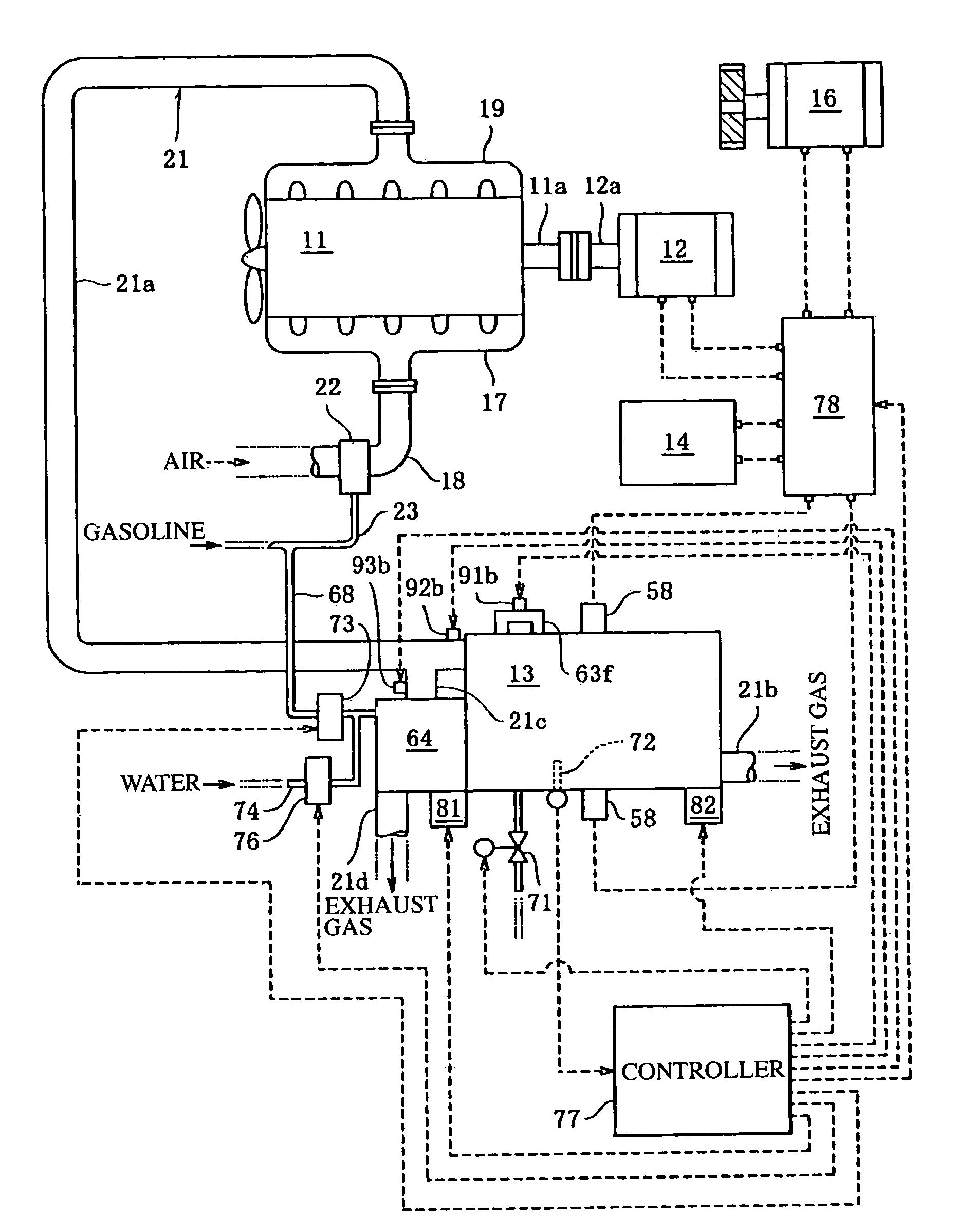
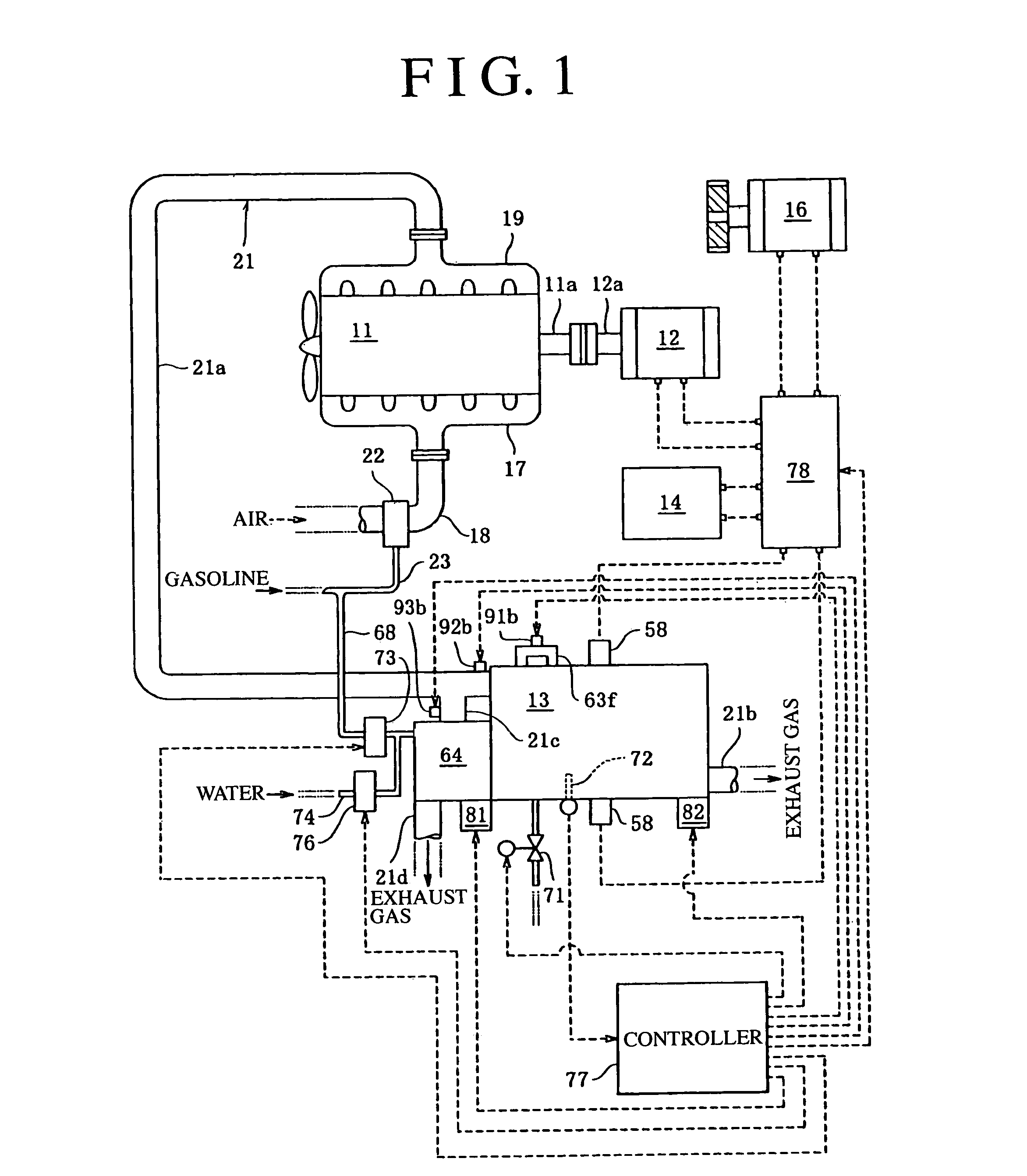
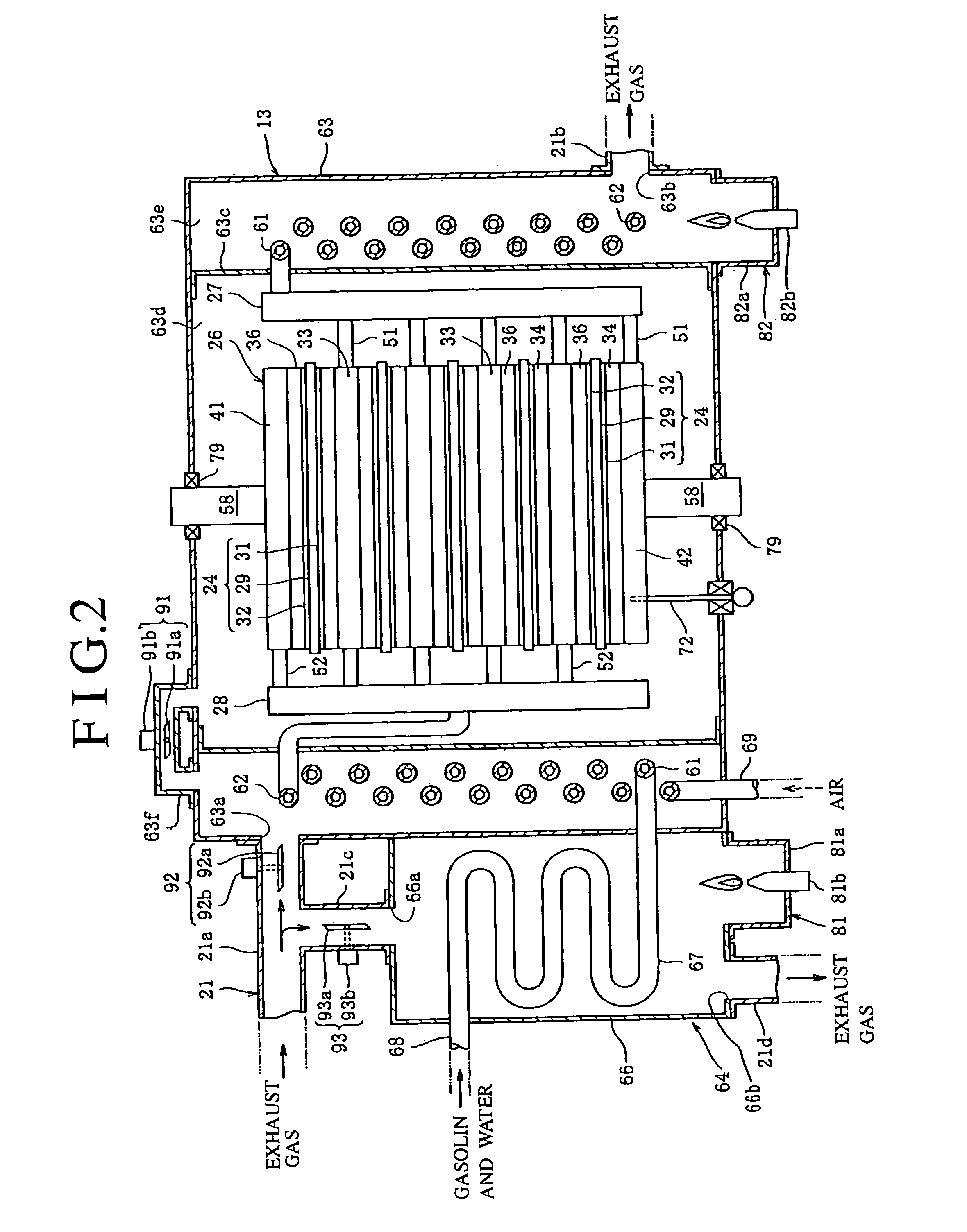
[0019]Further, as shown in FIGS. 1 and 2, a reformer 64 is provided near the fuel cell module 13. The reformer 64 includes a reforming case 66 into which the exhaust gas of the engine 11 is introduced, and a reforming pipe 67 housed in the reforming case 66 and filled with reforming particles at such a density that hydrocarbon can flow. The hydrocarbon passes through the reforming pipe 67 so that the hydrocarbon is reformed into the fuel gas of a low hydrocarbon group or the fuel gas of CO or H2, and is supplied to the fuel cell module 13. When the hydrocarbon, together with water, flows into the reforming pipe 67 of the reformer 64, the hydrocarbon and water are heated by the exhaust gas passing through the reforming case 66 and are vaporized, and become the fuel gas containing water vapor. The fuel gas containing the water vapor comes in contact with the reforming particles in the reforming pipe 67, is reformed into the fuel gas of the low hydrocarbon group, or the like, and is supplied to the fuel cell module 13. Since the reformer 64 is provided near the fuel cell module 13, the reformer 64 absorbs heat generated from the fuel cell module 13 at the time of electric power generation, and the fuel gas containing the water vapor is further efficiently reformed by the reforming particles in the reforming pipe 67 into the fuel gas of the low hydrocarbon group, or the like.
[0024]Further, as shown in FIGS. 1 and 2, a water supply pipe 74 is connected to the fuel supply pipe 68, and a water injector 76 for spraying water and supplying it to the fuel supply pipe 68 is provided to the water supply pipe 74. Thus, the liquid fuel or water can be quickly vaporized.
[0025]Further, as shown in FIG. 1, a module temperature sensor 72 for detecting the temperature of the fuel cell module 13 is inserted in the fuel cell module 13. When the module temperature sensor 72 detects that the fuel cell module 13 is heated by the exhaust gas of the engine 11 to reach the temperature at which the fuel cell module 13 can generate electric power, a controller 77 controls the fuel cell module 13 to start an electric power generating operation. When the fuel cell module 13 has a low temperature as at a time immediately after the start of the engine 11, the state is kept in which electric power generation by the fuel cell module 13 is stopped. When the temperature sensor 72 detects that the fuel cell module 13 is heated by the exhaust gas of the engine 11 and reaches the temperature at which electric power can be generated, the electric power generation by the fuel cell module 13 is started, so that efficient electric power generation by the fuel cell module 13 becomes possible.

Problems solved by technology

However, in the conventional fuel cell power generating system disclosed in JP-A-6-140065, since the raw material of the fuel gas supplied to the fuel cell is methanol, if this system is mounted in an automobile, there has been a disadvantage that refueling can not be carried out in a normal gasoline station.
Besides, in the conventional fuel cell power generating system, since the working temperature of the fuel cell is relatively low, there has been a problem that unless methanol is supplied to the fuel cell after it is completely reformed into H2 (hydrogen gas) by the reformer, the power generation efficiency of the fuel cell is lowered.
Further, in the conventional fuel cell power generating system, since the electrolyte layer is formed of the polymer film, there has been a problem that there is a fear that CO (carbon monoxide) is exhausted from the power generating cell, and the treatment of the carbon monoxide is troublesome.

Method used


Image

  • Hybrid power system including an engine and a fuel cell module
  • Hybrid power system including an engine and a fuel cell module
  • Hybrid power system including an engine and a fuel cell module

Examples


Embodiment Construction

[0035]Next, an embodiment of the invention will be described with reference to the drawings.

[0036]As shown in FIG. 1, a hybrid power system of the invention is mounted in an automobile. This hybrid power system includes an engine 11 using gasoline as fuel, a generator 12 an input shaft 12a which is coupled with a crank shaft 11a of the engine 11, a fuel cell module 13 which can generate electric power at 930° C. or lower, a secondary battery 14, and an electric motor 16. An intake pipe 18 is connected to an intake port of the engine 11 through an intake manifold 17, and an upstream side exhaust pipe 21a of an exhaust pipe 21 is connected to an exhaust port of the engine 11 through an exhaust manifold 19. A carburetor 22 for vaporizing gasoline to supply it to the intake pipe 18 is provided midway in the intake pipe 18, and a tip end of a refueling pipe 23, a base end of which is connected to a fuel tank (gasoline is stored), is connected to the carburetor 22. Gasoline vaporized by t...


PUM

PropertyMeasurementUnit
temperatureaaaaaaaaaa
mechanical poweraaaaaaaaaa

Abstract

A mixture of a fuel gas obtained by vaporizing hydrocarbon and air is burned in an engine 11 to generate mechanical power. The fuel gas obtained by reforming the hydrocarbon is supplied to a fuel electrode layer of a fuel cell module 13 in which plural electric power generating cells each including a solid electrolyte layer, and a fuel electrode layer and an air electrode layer disposed on both sides thereof are laminated, and the air or oxygen is supplied to the air electrode layer, so that the fuel cell module 13 is constructed to be capable of generating electric power at 930° C. or lower. One of or both of mechanical power generated by the engine 11 and electric power generated by the fuel cell module 13 are outputted. As a raw material of the fuel gas supplied to the fuel cell module, gasoline, light oil or the like which can be supplied in a normal gasoline station can be used.

Description

TECHNICAL FIELD[0001]The present invention relates to a hybrid power system using a fuel cell module of a solid oxide type.BACKGROUND OF THE INVENTION[0002]Conventionally, a fuel cell power generating system is constructed such that a raw material containing liquid fuel and water as its main ingredients is heated and decomposed by a burner of a reformer to generate hydrogen gas, a fuel cell in which a fuel electrode and an oxygen electrode are disposed on both sides of an electrolyte layer introduces the hydrogen gas generated by the reformer into the fuel electrode to generate electric power and supplies steady electric power to a specified load, a secondary battery supplies required electric power to the load at least at the time of load starting or the time of load variation, and power supply changeover means can switch between power supplied from the fuel cell and power supplied from the secondary battery (JP-A-6-140065). This fuel cell power generating system is constructed suc...

Claims


Application Information

Patent Timeline
Patent Type & Authority Patents(United States)
IPC IPC(8): H01M8/10B60K1/00F02B43/08H01M8/18B60L11/18B60L50/15B60W10/28B63H19/00B63H23/24F02B43/10H01M8/00H01M8/02H01M8/04H01M8/06H01M8/12H01M16/00
CPCB60K6/32B60L11/1881B60L11/1894B60W10/28F02B43/10H01M8/04022H01M8/04268H01M16/006B60L11/123Y02E60/563B63H19/00B63H23/24H01M4/9033H01M4/9066H01M8/0206H01M8/0612H01M8/1246H01M2008/1293H01M2250/407Y02T10/6217Y02T10/7077Y02T10/32Y10S903/905Y10S903/908Y02E60/50Y02T90/34Y02E60/525B60L50/61B60L58/30B60L58/34Y02E60/10Y02T10/30Y02T10/62Y02T10/70Y02T90/40Y02P70/50Y02T10/7072
Inventor AKIKUSA, JUNKOJI, HOSHINO
Owner MITSUBISHI MATERIALS CORP
Learn More