Optical systems utilizing optical fibers transmitting high power signal and a method of operating such systems

a technology of optical fibers and optical fibers, applied in the field of optical systems, can solve the problems of difficult spectrally sharpening of dichroic filters, relatively low capability of fibers to handle high-power multi-mode optical sources, and introduce power loss at the 3-level wavelength, etc., to achieve easy and efficient splicing to other optical fibers, reduce power loss, and reduce the effect of power loss

Active Publication Date: 2007-06-26
CORNING INC
View PDF9 Cites 9 Cited by
  • Summary
  • Abstract
  • Description
  • Claims
  • Application Information

AI Technical Summary

Benefits of technology

[0021]One advantage of the optical system of the present invention is its capability to produce large amount gain or handling large amounts of optical power, thus being capable for use in a high power laser or an optical amplifier, while eliminating power loss due to SRS or “a four level “signal. Another advantage of the optical fiber of the present invention is that because it eliminates the need to use larger core diameter fiber in high power applications, making splicing to other optical fibers easier and more efficient.
[0022]In some embodiments of the optical system of the present invention the optical fiber is a single polarization fiber that is employed to propagate the signal wavelength of interest within the SPB and to eliminate propagation of optical power in wavelengths associated with either SRS or, in a three level system, to eliminate signals associated with the four level gain.

Problems solved by technology

This type of fiber has relatively low capability of handling high power multimode optical sources due to the difficulty of efficiently coupling multimode light from a high power optical (light) source (also referred to herein as optical pump or pump) into the rare-earth doped fiber core.
However, dichroic filters are difficult to make spectrally sharp enough so that no additional loss is added at three-level wavelengths.
That is, such filters introduce power loss at the 3-level wavelengths.
Furthermore, these dichroic filters add further complexity and expense to the overall system.
While this approach increases pump power density to promote three-level inversion it makes it difficult and / or inefficient to couple pump power into the optical fiber and add complexity to the pump power coupling system.
Furthermore, when the optical fiber generates and propagates a high power optical signal and when the optical power exceeds Raman threshold level, the signal light is shifted to longer wavelength via Simulated Raman scattering, inducing power loss at the operating wavelength and preventing further power buildup.
However, optical fibers with low numerical apertures and large core diameters are very susceptible to the bend-induced losses.
In addition, because of non standard dimensions, these fibers are difficult to handle because they are not compatible with existing fibers or fiber handling technologies (fiber cleavers and fusion splices).
Finally, when such fiber is fusion spliced to an optical fiber with a smaller core diameter, the signal power does not couple effectively into a smaller core of the second optical fiber, and a large amount of signal power is lost at the splice due to mismatch between the core sizes.

Method used


Image

  • Optical systems utilizing optical fibers transmitting high power signal and a method of operating such systems
  • Optical systems utilizing optical fibers transmitting high power signal and a method of operating such systems
  • Optical systems utilizing optical fibers transmitting high power signal and a method of operating such systems

Examples


examples

The invention will be further clarified by the following examples.

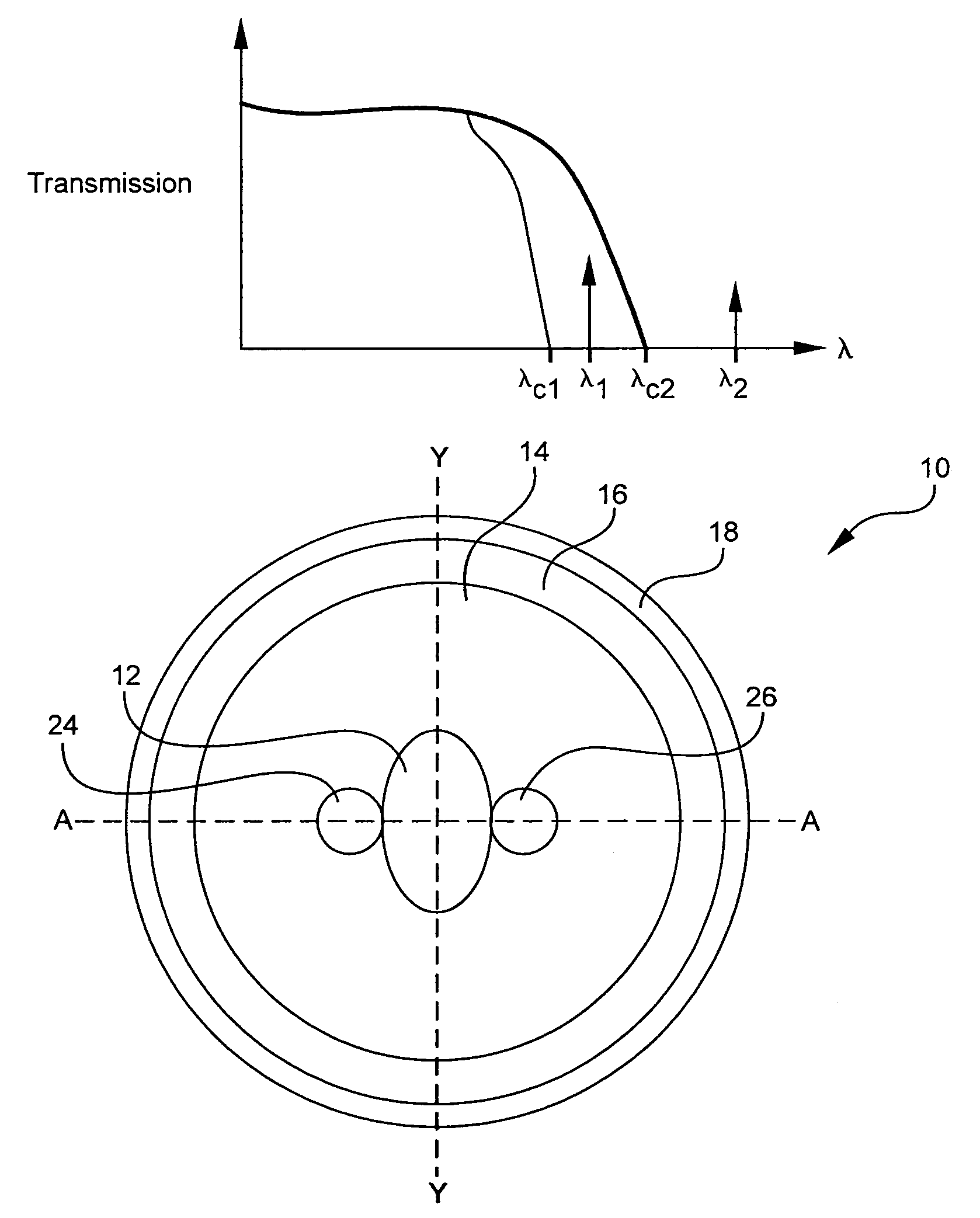
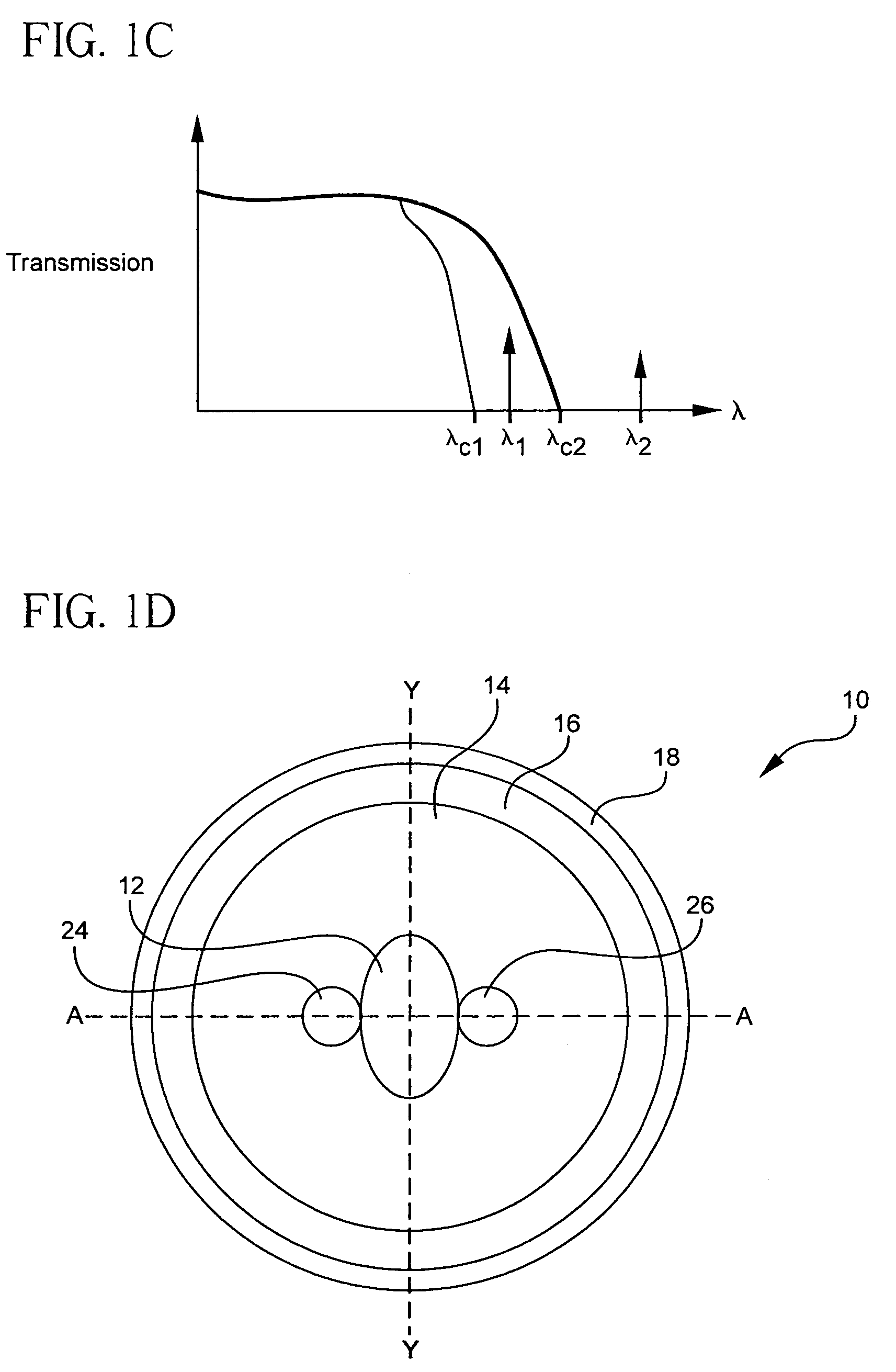
[0065]FIGS. 3A and 3B illustrate schematically a relative refractive index profile of the optical fiber of shown in FIG. 1D. More specifically, FIGS. 3A and 3B depicts optical fiber's refractive index percent delta (relative to that of the pure silica) vs. the distance measured from the core center. FIG. 3A illustrates schematically a refractive index profile taken across the region that does not contain the air holes, for example, along the line Y-Y of the fiber depicted in FIG. 1D. FIG. 3B illustrates schematically a refractive index profile of the same fiber, but taken across the region that contains the air hole 24 (for example, along the line A-A of the fiber depicted in FIG. 1D).

[0066]FIG. 3C illustrates measured refractive index profile (percent delta, relative to that of the pure silica) of another exemplary optical fiber of the present invention along the Y-Y axis, measured from the core center. This optical ...


PUM


Abstract

An optical system comprises an optical fiber with gain producing core with an index of refraction n1, surrounded by at least one cladding with an index of refraction n2, said cladding including at least one index reduced area with an index of refraction n2, such that n1>n2>n2, the core propagating a signal at a spatial fundamental mode at a signal wavelength λ1 and at a power level sufficient to generate optical power at a wavelength λ2, where λ2>λ1, and the at least one index reduced area in combination with the core provide has at least one cut-off fundamental spatial mode wavelength λC, and λ1<λC and λ2>λC.

Description

BACKGROUND OF THE INVENTION[0001]1. Field of the Invention[0002]The present invention relates generally to optical systems that utilize optical fiber for propagating high power optical signal, and more particularly to lasers, laser amplifiers and oscillators with a rare earth doped optical fiber operating in high power regime.[0003]2. Technical Background[0004]Optical fiber has become a favorite medium for telecommunications due to its high capacity and immunity to electrical noise. Single clad rare earth doped optical fiber has been widely used in the field of optical amplifiers and fiber lasers. This type of fiber has relatively low capability of handling high power multimode optical sources due to the difficulty of efficiently coupling multimode light from a high power optical (light) source (also referred to herein as optical pump or pump) into the rare-earth doped fiber core.[0005]To solve this problem and to increase the output power of fiber lasers, those of skill in the art ...

Claims


Application Information

Patent Timeline
Patent Type & Authority Patents(United States)
IPC IPC(8): G02B6/00G02B6/02G02B6/032
CPCH01S3/06754G02B6/02366G02B6/024G02B6/03633G02B6/03644H01S3/06729H01S3/06737H01S3/1618H01S3/1695
Inventor WALTON, DONNELL THADDEUSWANG, JIZENTENO, LUIS ALBERTOLI, MING-JUN
Owner CORNING INC
Why Eureka
Try Eureka