Catadioptric projection system for 157 nm lithography

a projection system and catadioptric technology, applied in the direction of instruments, lighting and heating equipment, photomechanical equipment, etc., can solve the problems of low numerical aperture, difficult mounting and adjustment face, and similar mounting and adjustment difficulties, so as to simplify the design of stressed qualities and more degrees of freedom

Inactive Publication Date: 2007-07-03
CARL ZEISS SMT GMBH
View PDF61 Cites 52 Cited by
  • Summary
  • Abstract
  • Description
  • Claims
  • Application Information

AI Technical Summary

Benefits of technology

[0016]A preferred embodiment according to claim 11 is a photolithographic reduction projection catadioptric objective including a first optical group including an even number of at least six mirrors, and a second at least substantially dioptric optical group more imageward than the first optical group including a number of lenses for providing image reduction. This increased number of mirrors gives more degrees of freedom to the correction and simplifies the design for stressed qualities.

Problems solved by technology

As optical lithography is extended into the vacuum ultraviolet (VUV), issues surrounding the laser linewidth and material availability could cause substantive delays to the development of a commercial 157 nm step / repeat or step / scan tool.
In addition, all but one of the six mirrors shown at FIG. 3 are cut off sections of a bodies of revolution, yielding mounting and adjustment face difficulties.
The objective described in the '035 application also exhibits a low numerical aperture and offers similar mounting and adjustment difficulties as described above with respect to the '528 application.
However, these systems have a serious drawback since the size of this beam splitting element becomes quite large as the numerical aperture is increased up to and beyond 0.65 to 0.70, making the procurement of bulk optical material with sufficient quality (in three-dimensions) a high risk endeavor.
This problem is exacerbated as wavelengths are driven below 193 nm because the selection of material that can be manufactured to lithographic quality is severely limited.
However, it is difficult to achieve an adequately high numerical aperture (e.g., U.S. Pat. Nos. 4,685,777, 5,323,263, 5,515,207 and 5,815,310, which are incorporated by reference), or to achieve a fully coaxial configuration, instead of relying on the use of folding mirrors to achieve parallel scanning (e.g., U.S. Pat. No. 5,835,275 and EP 0 816 892, which are incorporated by reference) and thereby complicating the alignment and structural dynamics of the system.

Method used


Image

  • Catadioptric projection system for 157 nm lithography
  • Catadioptric projection system for 157 nm lithography
  • Catadioptric projection system for 157 nm lithography

Examples


Embodiment Construction

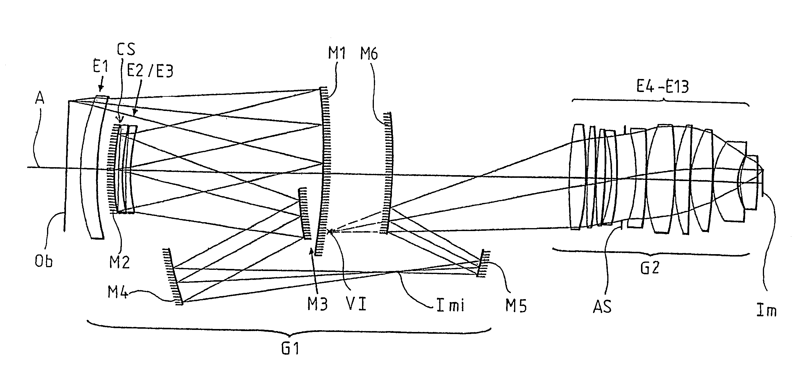
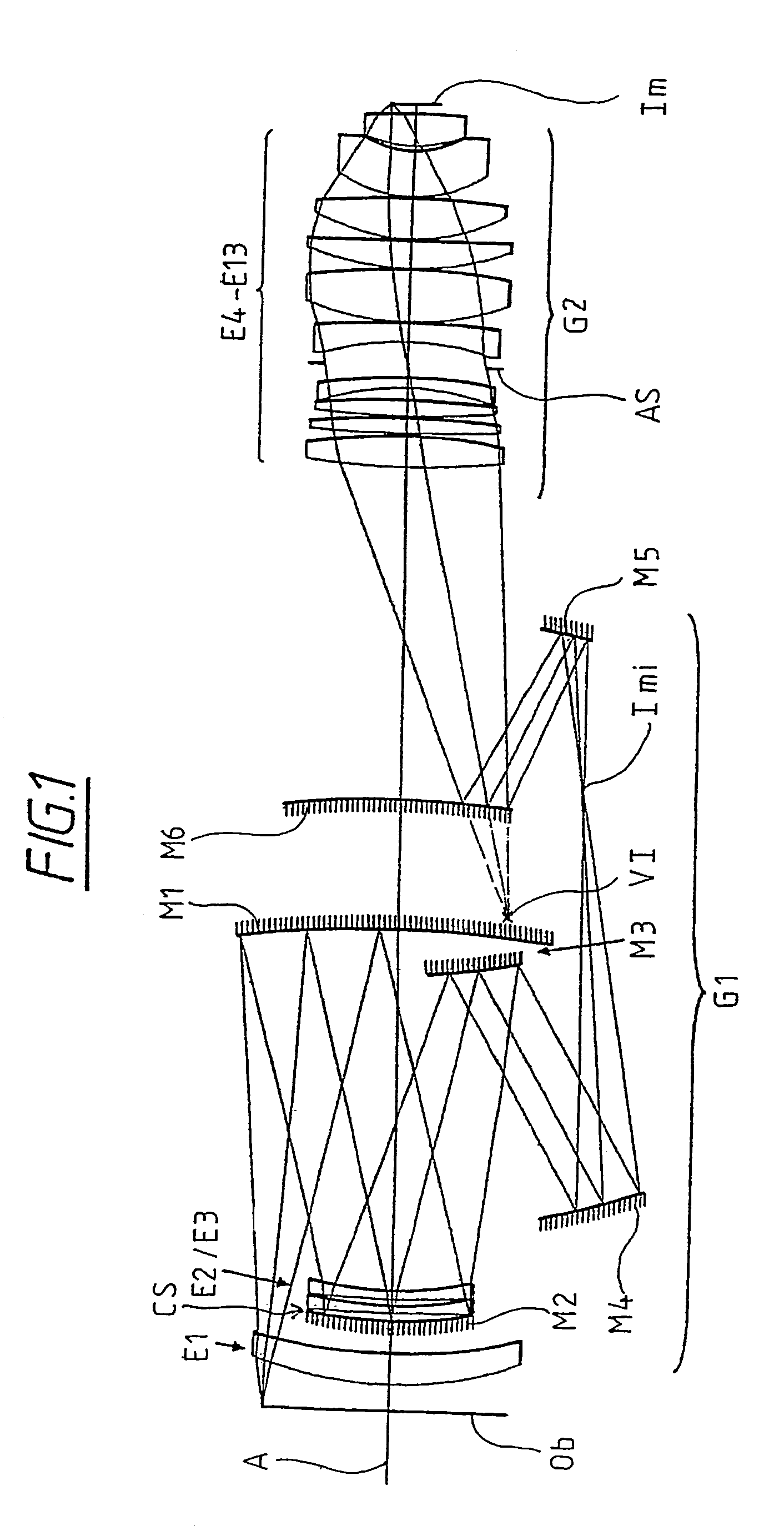
[0026]A catadioptric projection system according to a preferred embodiment herein is schematically shown at FIG. 1 and includes two distinct optical groups G1 and G2. Group G1 is a catadioptric group including mirrors M1–M6 and lenses E1–E3, as shown in FIG. 1. An object or mask plane Ob is disposed to the left of group G1 in FIG. 1 or optically before group G1. Group G2 is disposed optically after group G1 and to the right of group G1 in FIG. 1. An image or wafer plane Im is disposed optically after group G2 and to the right of group G2 in FIG. 1.

[0027]Group G1 functions by correcting field aberrations and providing a conjugate stop position for correction of axial chromatic aberration. Group G2 is a dioptric group including lens elements E4–E13, as also shown in FIG. 1. Group G2 lies aft of G1, or optically nearer the image plane of the system, enabling the system to achieve numerical apertures in excess of 0.65, 0.70 and even 0.75. This catadioptric system achieves a high numeric...


PUM

PropertyMeasurementUnit
angleaaaaaaaaaa
wavelengthaaaaaaaaaa
wavelengthsaaaaaaaaaa

Abstract

A photolithographic reduction projection catadioptric objective includes a first optical group G1 including an even number of at least four mirrors M1–M6; and a second at least substantially dioptric optical group G2 imageward than the first optical group G1 including a number of lenses E4–E13. The first optical group G1 provides compensative axial aberrative correction for the second optical group G2 which forms an image with a numerical aperture of at least substantially 0.65, and preferably at least 0.70 or 0.75. Six mirror examples are shown.

Description

RELATED APPLICATIONS[0001]This application is a continuation of U.S. patent application Ser. No. 10 / 444,897, filed May 23, 2003 now abandoned, which is (1) a continuation of International Application Ser. No. PCT / EP01 / 13851, filed Nov. 28, 2001 and published in English on Jun. 6, 2002, which claims priority from U.S. Provisional Patent Application Ser. No. 60 / 253,508, filed Nov. 28, 2000 and from U.S. Provisional Patent Application Ser. No. 60 / 250,996, filed Dec. 4, 2000, and (2) a Continuation-in-Part of U.S. patent application Ser. No. 09 / 761,562, filed Jan. 16, 2001 (now U.S. Pat. No. 6,636,350) which claims the benefit of priority to U.S. provisional patent application Ser. No. 60 / 176,190, filed Jan. 14, 2000, all of the aforementioned patent applications and patents are hereby incorporated by reference in their entirety.BACKGROUND OF THE INVENTION[0002]1. Field of the Invention[0003]The invention relates to projection systems for photolithography, and particularly to catadioptr...

Claims


Application Information

Patent Timeline
Patent Type & Authority Patents(United States)
IPC IPC(8): G02B5/08G02B17/08G02B13/24G03F7/20H01L21/027
CPCG02B17/0844G02B17/0892G03F7/70225G03F7/70275G03F7/70358
Inventor HUDYMA, RUSSELL
Owner CARL ZEISS SMT GMBH
Why Eureka
Try Eureka