Fire detection method and fire detector therefor

a fire detection and detector technology, applied in the field of fire detection methods and fire detectors therefor, can solve the problems of insufficient sensitivity of small and very small particles, inability to meet the actual conditions of fire detection, and difficulty in recognizing open fires in due tim

Active Publication Date: 2007-07-03
NOVAR PLC
View PDF11 Cites 20 Cited by
  • Summary
  • Abstract
  • Description
  • Claims
  • Application Information

AI Technical Summary

Benefits of technology

[0017]To protect the photodetectors from direct illumination by the LEDs and from illumination by radiation reflected on the walls of the measuring chamber and to keep the illumination of the measuring volume by reflected radiation as low as possible, every LED and every photodetector is appropriately located in its own, individual tube body. Moreover, diaphragms and radiation traps are arranged outside of the measuring volume between the LEDs and the photodetectors.

Problems solved by technology

Although the latter is correct, it does not fulfill the actual conditions in recognizing fires according to the scattered light principle.
The known method and the detector which operates according to this method have a common feature with all other known constructions of scattered-light fire detectors which operate on the basis of infrared light, which feature is the disadvantage of an inadequate sensitivity for small and very small particles.
This makes it more difficult to recognize open fires in due time, and especially wood fires whose smoke is characterized by a very small particle size.
Due to this radioactive preparation, the production of ionization fire detectors is complex and their use is unpopular and even generally prohibited in a number of countries.

Method used


Image

  • Fire detection method and fire detector therefor
  • Fire detection method and fire detector therefor
  • Fire detection method and fire detector therefor

Examples


second embodiment

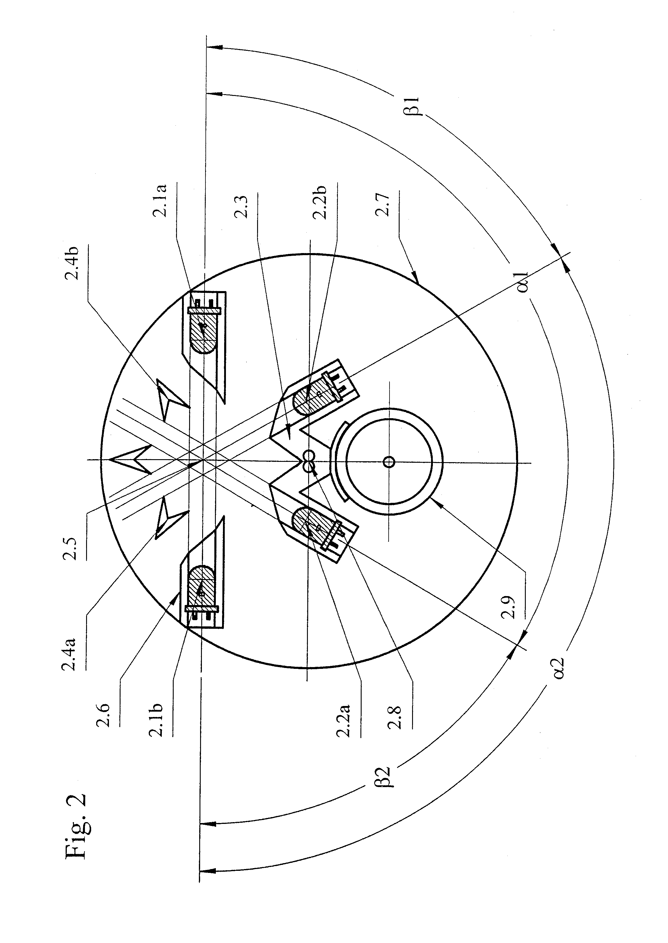
[0030]FIG. 2 shows the detector with the same components as in FIG. 1, but with a different geometrical arrangement. In order to explain this arrangement in closer detail, the first digit of the respective reference numeral is provided here with “2” instead of “1”. In contrast to FIG. 1, only the radiation axes of the infrared-radiating LED 2.1a and the blue-radiating LED 2.1b which go through the measuring center 2.5 will coincide. The receiving axis of the photodiode 2.2a encloses an angle α1=120° with the radiation axis of LED 2.1a and with the radiation axis of the blue-radiating LED 2.1b an angle β2=60°. The receiving axis of the photodiode 2.2b encloses conversely with the radiation axis of the infrared-radiating LED 2.1a an angle α1=60° and with the radiation axis of the blue-radiating LED 2.1b an angle α2=120°. Accordingly, the first photodiode 2.2a measures the forward scattered radiation of the “infrared” LED 2.1a and the backward scattered radiation of the “blue” LED 2.1b...

first embodiment

[0031]The photodiodes 2.2a and 2.2b can exchange their positions with the LEDs 2.1a and 2.1b, so that the two photodiodes are situated precisely opposite with respect to the measuring center 2.5. This geometrical arrangement of the four components, i.e., that of the two LEDs and the two photodiodes, is less favorable than that of FIG. 1 because only 75% of the four measured scattered radiations orginate from the same measuring volume. This is illustrated by the intersecting surfaces between the beams which are shown by omitting the angular dependency both of the intensity of the emitted radiations as well as the sensitivity of the photodiodes as well as the diffraction effects which occur unavoidably on the edges. In the case of detectors which (as in the embodiment) comprise further sensors such as 2.8 and 2.9, there is an additional factor that the measuring center 2.5 is disposed in a strongly eccentric fashion with respect to the center of the base plate 2.7. This leads to the c...

third embodiment

[0032]FIG. 3 shows the detector with the same components as in FIG. 2, but with a different geometrical arrangement. In order to illustrate this in closer detail, the first digit of the respective reference numeral is provided here with “3” instead of “2”. In contrast to FIG. 1, only the receiving axes of the photodiodes 3.2a and 3.2b coincide which pass through the measuring center 3.5. These receiving axes form the main axis. The “infrared” LED 3.1a encloses with the latter an acute angle α1=60° and an obtuse angle β1=120°. The “blue” LED 3.1b is situated opposite of the “infrared” LED 3.1a with respect to the main axis, which “blue” LED accordingly encloses with the main axis an acute angle β2=60° and an obtuse angle α2=120°. As a result, the photodiode 3.2a receives both the infrared forward scattered radiation as well as the blue forward scattered radiation, whereas the photodiode 3.2b receives both the infrared backward scattered radiation as well as the blue backward scattere...


PUM

PropertyMeasurementUnit
wavelengthaaaaaaaaaa

Abstract

The sensitivity of scattered-light fire detectors for small particles can be increased substantially when blue light is introduced into the measuring volume in addition to an infrared radiation and the scattered radiation produced by the particles is measured and evaluated separately from each other in the infrared and blue region both in the forward scattering region as well as in the backward scattering region. This can be realized by a fire detector that includes two transmitter LEDs (2.1a, 2.1b) and two photodetectors (2.2a, 2.2b), with these components being arranged such that the photodetectors receive both the forward scattered radiations as well as the backward scattered radiations of the longer and shorter wavelengths separately from each other. A multi-channel evaluation circuit is provided downstream of the photodetectors.

Description

BACKGROUND OF THE INVENTION[0001]1. Field of the Invention[0002]The invention relates to a method for recognizing fires according to the scattered light principle by pulsed emission of a radiation of a first wavelength along a first radiation axis as well as a radiation of a second wavelength which is shorter than the first wavelength along a second radiation axis into a measuring volume and by measuring the radiation scattered on the particles located in the measuring volume under a forward scattering angle of more than 90° and under a backward scattering angle of less than 90°. The invention further relates to a scattered-light fire detector for performing this method.[0003]2. Description of the Related Art[0004]A scattered-light detector is known from WO 01 / 59 737 which is provided especially for installation in ventilation and air-conditioning conduits, which operates according to the aforementioned method and where a first light-emitting diode (LED) emits infrared light and a s...

Claims


Application Information

Patent Timeline
Patent Type & Authority Patents(United States)
IPC IPC(8): G01N15/02G08B17/107
CPCG08B17/107G08B17/113
Inventor POLITZE, HEINERSPRENGER, RALFKRIPPENDORF, TIDOOLLIK, WALDEMAR
Owner NOVAR PLC
Why Eureka
Try Eureka