
Permeable membrane diaphragm of different layers for electroytic cells

a technology of electrolysis cell and membrane, applied in the direction of ion-exchanger, filtration separation, separation process, etc., can solve the problems of short life of the diaphragm, polymeric fibers can hardly form micropores, and danger of explosion, etc., to achieve easy plugging in operation, low cost, and low strength

Inactive Publication Date: 2007-07-10
HARBIN HUAER CHEM
View PDF2 Cites 2 Cited by
  • Summary
  • Abstract
  • Description
  • Claims
  • Application Information

AI Technical Summary

Benefits of technology

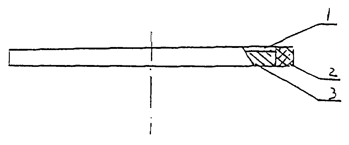
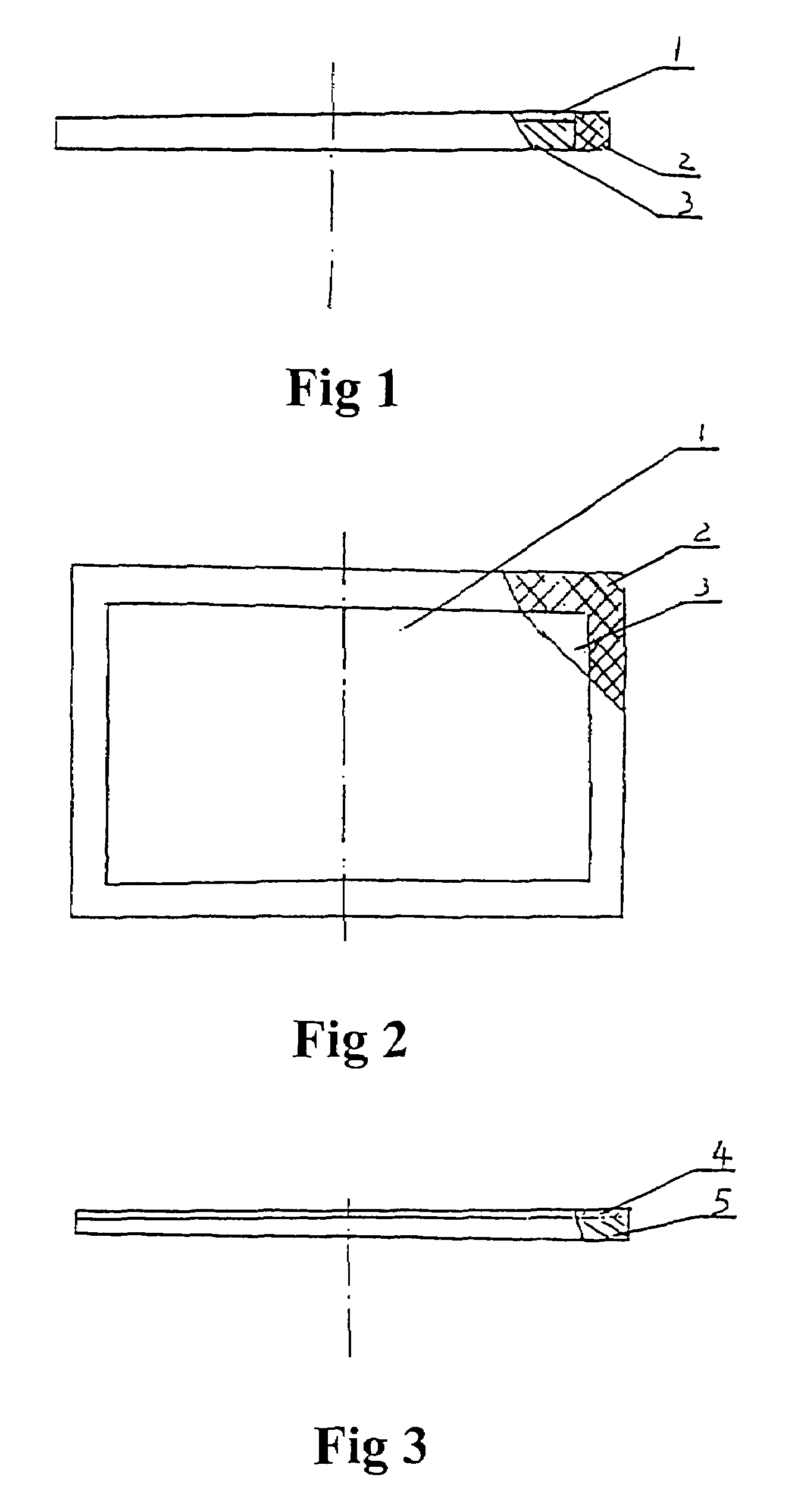
[0011]The object of the present invention is to overcome the disadvantages of the prior art, such as the diaphragm is of high cost, low strength and easily to be plugged in operation. The present invention provides a permeable membrane diaphragm of different layers for electrolytic cells. The diaphragm of the present invention has an asymmetric structure formed by different layers. The diaphragm has a thin layer with very small pore size on the side near the anode. This layer has low electric resistance and high flow resistance and can prevent insoluble particles entering into the layer. While, the diaphragm has a thick layer with larger pore size on the side near the cathode, so it can discharge the deposition of hydroxide easily without sacrifice its capability of restricting the diffusion of OH— groups from the cathodic compartment to the anodic compartment and at the same time, the thick layer renders higher strength to the diaphragm. The diaphragm of the present invention is more profitable than prior polymer or asbestos diaphragm and can eliminate the pollution of asbestos.
[0012]The diaphragm of the present invention can bear an up to 3000 A / m2 and frequently changed current density, and thus increases the productivity and decrease the production cost.SUMMARY OF THE INVENTION

Problems solved by technology

Thus, the two gases can't mix and react with each other to cause the danger of explosion.
However, the lifetime of diaphragm is short because of the low strength of asbestos.
However, unlike asbestos, the polymeric fibers of these diaphragms do not have much branches and scales on their surfaces, and thus these polymeric fibers can hardly form micro pores.
Because the process is very complex, the production cost is very high.
Meanwhile, since a large portion of the fillers is removed to provide desired porosity to the diaphragm, the finished diaphragm is inherently weak.
To offset this problem, the thickness of the diaphragm is increased and it leads to increase the consumption of the precious micro-porous PTFE.
The operation voltage and the consumption of energy are also increased.
Since the consumption of the precious material PTFE is large and the pores formed thereon do not connect each other, the cost of the diaphragm is high and its resistance will increase rapidly if the diaphragm is plugged.
This process also has the above-mentioned disadvantages, that is, it is complicated to control the homogeneity of the mixture and the uniformity of the pores size.
Meanwhile, since the fillers, which constitute a large part of the diaphragm structure are removed to provide the porosity, the finished diaphragm is inherently weak.
To offset the problem, the finished diaphragm must be undesirably thick.
So a lot of precious PTFE is used and thus the cost of the diaphragm is high.
Although the diaphragm plugging may be reduced, but the extent of reduction is limited.

Method used


Image

  • Permeable membrane diaphragm of different layers for electroytic cells
  • Permeable membrane diaphragm of different layers for electroytic cells

Examples


example 1

[0043]A PTFE plate was extended at two dimensions and treated with an organic surfactant to make a flow-controlling permeable layer-PTFE hydrophilic micro-porous membrane. It has a mean pore diameter of 0.1 μm and a thickness of 0.1 mm; Then, polypropylene was used as raw material to make a diffusion-restricting permeable layer-polypropylene perforate film. Its mean pore diameter is 12 μm and thickness is 1 mm; Then the polypropylene perforate film was covered by the PTFE hydrophilic micro-porous membrane and a glass cloth was used as a protective layer to cover the surface of the PTFE hydrophilic micro-porous membrane. Finally the above-said membranes were bonded to a PTFE frame with an adhesive to obtain the permeable membrane diaphragm of different layers of the present invention. When the current density was 2000 A / m2, temperature was 95° C., and the concentration of NaOH in the electrolytic solution was 120 kg / m3, the voltage of the diaphragm was 0.10 v.

example 2

[0044]A PTFE hydrophilic micro-porous membrane was made by the same method as described in example 1. Its mean pore diameter is 0.5 μm and thickness is 0.15 mm; a diffusion-restricting permeable layer was made from Nylon 6 with mean pore diameter of 15 μm and thickness of 0.8 mm. When the current density was 2000 A / m2, temperature was 95° C., and the concentration of NaOH in the electrolytic solution was 120 kg / m3, the diaphragm, which contained the above-said layers, had a voltage of 0.08 v.

example 3

[0045]Three PTFE hydrophilic micro-porous membranes were made by the same method as described in example 1. The membranes are in the same size. For each membrane, its thickness is 30 μm and a mean pore diameter is 1.5 μm. The three membranes were hot-pressed together to form the flow-controlling permeable layer; A PTFE perforate film was made from a PTFE plate with mean pore diameter of 8 μm and thickness of 0.4 mm. When the current density was 2000 A / m2, temperature was 95° C., and the concentration of NaOH in the electrolytic solution was 120 kg / m3, the voltage of the diaphragm was 0.10 v.


PUM

PropertyMeasurementUnit
mean pore diameteraaaaaaaaaa
current densityaaaaaaaaaa

Abstract

The present invention relates to a permeable membrane diaphragm of different layers for electrolytic cell, especially for chloro-alkali electrolytic cell. The diaphragm is asymmetric, which comprises at least two layers: a flow-controlling permeable layer comprising micro-porous fluoropolymer, especially PTFE, and a diffusion-restricting permeable layer comprising porous film, sheet or cloth made of anticorrosive materials, preferably polypropylene. The flow-controlling layer is mounted near the anode, and the diffusion-restricting layer is mounted near the cathode. The mean pore diameter of the diffusion-restricting layer is at least 5 times more than that of the flow-controlling layer and the thickness of the diffusion-restricting layer is at least 1 times more than that of the flow-controlling layer. The pore diameter of said flow-controlling layer ranges from 0.1–2.0 μm, and its thickness is 0.03–0.2 mm. The pore diameter of said diffusion-restricting layer ranges from 5–50 μm, and its thickness is 0.3–2 mm. The above two layers can also be made of more than one similar thinner membranes respectively.

Description

FIELD OF THE INVENTION[0001]The present invention relates to a permeable membrane diaphragm of different layers, especially relates to the permeable membrane diaphragm of different layers for electrolytic cells used in chloro-alkali industry.PRIOR ART[0002]Diaphragm electrolytic cells are applied in the chloro-alkali industry to electrolyze brine for producing chlorine on the anode and producing caustic alkali and hydrogen on the cathode. The diaphragm in the electrolytic cell separates the cathode from the anode, and permits the electrochemical reactions happen respectively to produce hydrogen or chlorine on the different electrodes. Thus, the two gases can't mix and react with each other to cause the danger of explosion. The electrolytic solution flows from the anodic compartment into the cathodic compartment through the diaphragm by the pressure drop that is formed by the difference between the levels of the anodic solution and the cathodic solution. The diaphragm controls the fl...

Claims


Application Information

Patent Timeline
Patent Type & Authority Patents(United States)
IPC IPC(8): C25B13/04C25B13/08
CPCC25B13/08
Inventor WANG, GUOCHENG
Owner HARBIN HUAER CHEM
Learn More