Dielectric information apparatus, tape-like medium recording/reproducing apparatus and disc-like medium recording/reproducing apparatus

Inactive Publication Date: 2007-07-10
PIONEER CORP +1
View PDF44 Cites 22 Cited by
  • Summary
  • Abstract
  • Description
  • Claims
  • Application Information

AI Technical Summary

Benefits of technology

[0039]This alternation signal is intended to give an oscillating electric field of a predetermined frequency to the polarization state and read out from a reproducing signal the recorded information at a high S/N ratio using this alternating current signal. However, if this alternation signal enters the oscillating device, it interferes with the oscillating device causing an oscillatory disturbance. Moreover, if a plurality of the first electrodes are placed in the dielectric information apparatus and a plurality of alternation signals with different fre

Problems solved by technology

As each resonator is relatively large in size, It is difficult to miniaturize the apparatus while integrating the

Method used


Image

  • Dielectric information apparatus, tape-like medium recording/reproducing apparatus and disc-like medium recording/reproducing apparatus
  • Dielectric information apparatus, tape-like medium recording/reproducing apparatus and disc-like medium recording/reproducing apparatus
  • Dielectric information apparatus, tape-like medium recording/reproducing apparatus and disc-like medium recording/reproducing apparatus

Examples


first embodiment

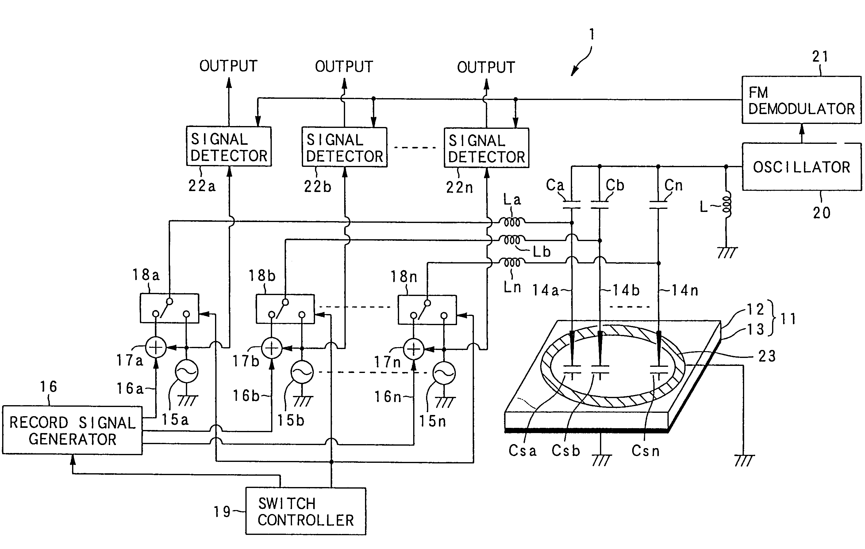
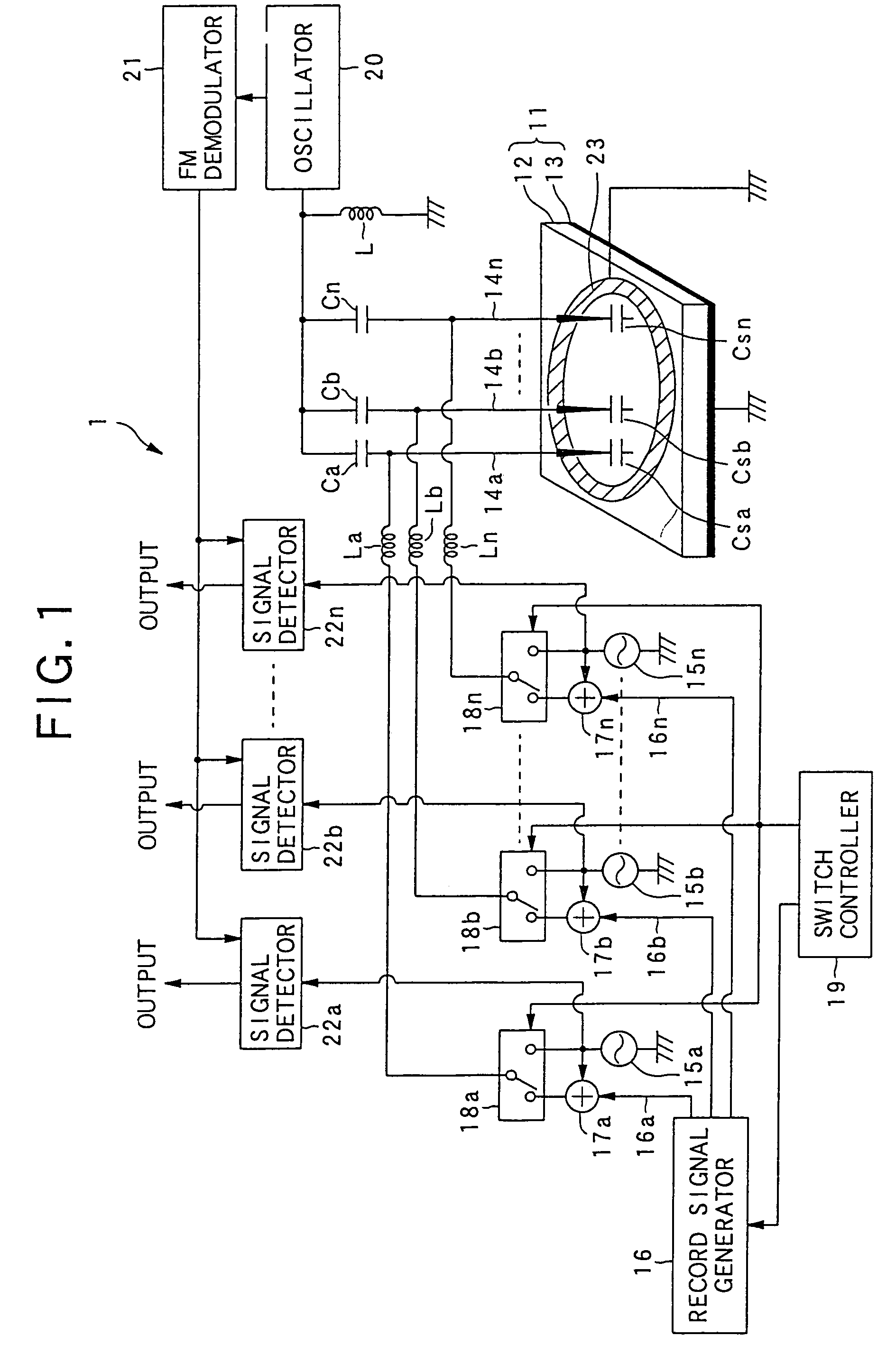
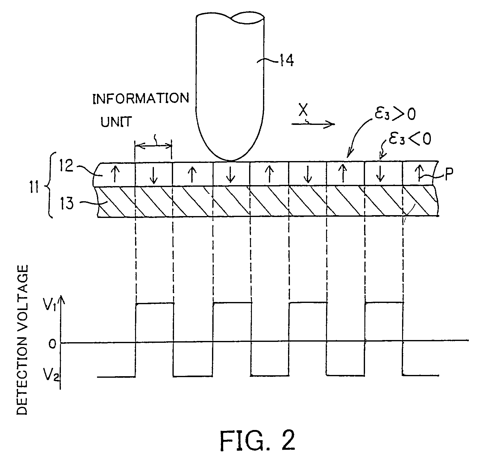
[0070]At first, the dielectric information apparatus in the first embodiment is described with reference to FIGS. 1 to 4. FIG. 1 is a view showing the configuration of the first embodiment, FIG. 2 is a view describing a relation between a polarization state of a dielectric substance and an output voltage, FIG. 3 is a view describing an action of an electrode placed around a probe, and FIG. 4 is a view describing a configuration of a lock-in amplifier used for detecting a signal and a signal detecting operation of the lock-in amplifier.

[0071]This embodiment is the dielectric information apparatus having a recording / reproducing function which includes: a configuration of a recording system for using a dielectric substance formed on a conductor substrate as a record medium, and applying an electric field to a small area of the dielectric substance, thereby matching a direction of a polarization with a predetermined direction, and thereby making the small area function as an information...

second embodiment

[0120]A second embodiment will be described below with reference to FIG. 5. This embodiment relates to a dielectric information apparatus that is established for recording information on a dielectric record medium and reproducing the information while recording it.

[0121]A dielectric information apparatus 2 includes: the alternating current signal generators 15a to 15n for generating the alternating current signals applied to the probes 14a to 14n; the record signal generator 16 for generating the record signals; the adders 17a to 17n for superimposing the signals from the record signal generator 16 and the signals from the alternating current signal generators 15a to 15n on each other; the inductors La to Ln for introducing the record signals to the probes 14a to 14n; the inductor L for constituting a resonating circuit together with the capacitances Csa to Csn; the oscillator 20 that oscillates on the basis of the resonance frequency of the resonating circuit; the FM demodulator 21...

third embodiment

[0125]A third embodiment will be described below with reference to FIG. 6. This embodiment relates to a dielectric information apparatus that is established for recording information on a dielectric record medium.

[0126]A dielectric information apparatus 3 in this embodiment includes: the alternating current signal generators 15a to 15n for generating the alternating current signals applied to the probes 14a to 14n; the record signal generator 16 for generating the record signals; the adders 17a to 17n for superimposing the signals from the record signal generator 16 and the signals from the alternating current signal generators 15a to 15n on each other.

[0127]The record signals are generated by the record signal generator 16, and superimposed on the alternating current signals of the alternating current signal generators 15a to 15n, and sent to the probes 14a to 14n at the time of the recording. The applied voltage causes the electric field to be induced between the probe 14 and the ...


PUM


Abstract

An example dielectric information apparatus is provided with a plurality of electrodes for recording information in a small area of a dielectric substance and an earthed electrode. The electrodes are placed such that the dielectric substance is sandwiched therebetween. The dielectric information apparatus reads out the information recorded in the small area of a dielectric thin film by applying alternating current signals to the first electrodes. The polarization direction of the small area and the direction of an applied electric field decide the dielectric constant of the small area, and the oscillation frequency of an oscillator is determined by a capacitance Cs corresponding to the dielectric constant. An oscillation signal of the oscillator is demodulated at an FM demodulator, and the information is detected from the demodulated signal at a signal detector. When recording, record signals are applied to the first electrodes, and the polarization direction is set to correspond to the record signals.

Description

BACKGROUND OF THE INVENTION[0001]1. Field of the Invention[0002]The present invention relates to dielectric information apparatus such as a recording apparatus for recording information in a small area of a dielectric substance, a reproducing apparatus for reproducing information recorded in a small area of a dielectric substance, and a recording / reproducing apparatus for recording information in and reproducing it from a small area of a dielectric substance.[0003]2. Description of the Related Art[0004]In recent years, many kinds of ferroelectric materials and piezoelectric materials have been developed and used for a supersonic, an optical device and a memory and the like. In association with it, a development of methods of measuring a residual polarization distribution of the ferroelectric material and a local anisotropy of the piezoelectric material has been advanced. With regard to the development in this field, the inventors of this application have developed a scanning nonline...

Claims


Application Information

Patent Timeline
IPC IPC(8): G11B7/00G11C11/24G11B9/00G11B9/02G11B9/08G11B9/14G11B11/08G11B25/06G11C11/22
CPCB82Y10/00G11B9/02G11B9/08G11B9/14G11B9/1472G11B9/149G11B11/08G11B25/06
Inventor CHO, YASUOONOE, ATSUSHI
Owner PIONEER CORP
Why Eureka
Try Eureka