Complex objective lens compatible with information media of different thicknesses

a technology of information media and complex objective lens, which is applied in the field of complex objective lens, can solve the problems of not revealing a scheme of reducing simultaneously the movement of the focal point position, and the wavelength selection phase plate does not have a lens power, so as to achieve high light use efficiency

Active Publication Date: 2007-07-17
PANASONIC CORP
View PDF49 Cites 29 Cited by
  • Summary
  • Abstract
  • Description
  • Claims
  • Application Information

AI Technical Summary

Benefits of technology

[0029]Therefore, with the foregoing in mind, it is an object of the present invention to provide a complex objective lens having a high light use efficiency, that realizes compatible reproducing and compatible recording between an optical disk designed for a red light beam with a wavelength λ2 (typically, about 660 nm) at a base thickness 0.6 mm and an optical disk designed for a blue light beam at a wavelength λ1 (typically, about 405 nm) at a base thickness of 0.1 mm.
[0040]In order to achieve the above-mentioned object, a third complex objective lens according to the present invention includes a hologram and a refraction type lens, wherein the hologram has a grating with a sawtooth cross-section formed in at least an inner circumferential portion, and a depth h1 of the sawtooth cross-section gives a difference in optical path length of about 2 wavelengths to a first light beam having a wavelength λ1 in a range of 390 nm to 415 nm to allow the first light beam to generate +2nd-order diffracted light most strongly, and allows a second light beam having a wavelength λ2 in a range of 630 nm to 680 nm to generate +1st-order diffracted light most strongly.
[0041]In order to achieve the above-mentioned object, a fourth complex objective lens according to the present invention includes a hologram and a refraction type lens, wherein the hologram has a grating with a sawtooth cross-section formed in at least an inner circumferential portion, and a depth h2 of the sawtooth cross-section gives a difference in optical path length of about one wavelength to a second light beam having a wavelength λ2 in a range of 630 nm to 680 nm to allow the second light beam to generate +1st-order diffracted light most strongly, and allows a first light beam having a wavelength λ1 in a range of 390 nm to 415 nm to generate +2nd-order diffracted light most strongly.
[0042]In order to achieve the above-mentioned object, a fifth complex objective lens according to the present invention includes a hologram and a refraction type lens, wherein the hologram has a grating with a sawtooth cross-section formed in at least an inner circumferential portion, and a depth h4 of the sawtooth cross-section gives a difference in optical path length larger than 1.7 wavelengths and smaller than 2 wavelengths to a first light beam having a wavelength λ1 in a range of 390 nm to 415 nm to allow the first light beam to generate +2nd-order diffracted light most strongly, and allows a second light beam having a wavelength λ2 in a range of 630 nm to 680 nm to generate +1st-order diffracted light most strongly.
[0046]In the second to sixth complex objective lenses, the hologram is configured so as to have a function as a convex lens in order to reduce a change in a focal length with respect to a change in the wavelength λ1 in a case of condensing the first light beam through a base with a thickness t1.
[0047]In the first to sixth complex objective lenses, in order to place a focal point position on an optical disk side away from the complex objective lens, the hologram is configured so as to have a larger function as a convex lens compared with the case of condensing the second light beam passing through an inner circumferential portion of the hologram through the base with the thickness t2, in a case of condensing the first light beam through the base with the thickness t1, or the hologram is configured so as to have a smaller function as a convex lens compared with a case of condensing the first light beam through the base with the thickness t1, in a case of condensing the second light beam passing through the inner circumferential portion of the hologram through the base with the thickness t2. Because of this, the focal point position on the optical disk side can be placed away from the complex objective lens, i.e., a working distance can be enlarged.

Problems solved by technology

In this case, there is a problem that the amount of aberration caused by the inclination (i.e., tilt) of an optical axis is increased.
However, this reflectivity is guaranteed only with respect to red light, and is not guaranteed at the other wavelengths.
Thus, the first conventional example does not disclose the configuration in which a light use efficiency is enhanced further when different kinds of optical disks are made compatible using, in particular, red light and blue light.
However, the first conventional example does not disclose a scheme of reducing simultaneously the movement of a focal point position caused by a change in wavelength with respect to each of at least two kinds of optical disks.
However, the wavelength selection phase plate does not have a lens power.
Furthermore, as in the second conventional example, when it is attempted to realize all the lens powers with respect to dispersed red light, a large aberration occurs while an objective lens is moved (e.g., follows a track), resulting in degradation of recording / reproducing characteristics.
In the third conventional example, since objective lenses are switched, it is required to use a plurality of objective lenses, which increases the number of parts, and makes it difficult to miniaturize an optical head.
Furthermore, the requirement of a switching mechanism also makes it difficult to miniaturize an apparatus.
Furthermore, the reflective surface of a mirror is composed of a surface having a radius of curvature (i.e., a spherical surface); however, the spherical surface is not sufficient for correcting the difference in base thickness and the difference in wavelength, and high-order aberration (5th-order or higher) cannot be reduced sufficiently.
When the fifth conventional example is applied directly to a red light beam and a blue light beam, diffraction efficiencies of the same order cannot be enhanced simultaneously because of a large difference in wavelength, and consequently, the use efficiency of light is decreased.
More specifically, at least two photodetectors are required, which increase the number of parts, leading to an increase in cost.

Method used


Image

  • Complex objective lens compatible with information media of different thicknesses
  • Complex objective lens compatible with information media of different thicknesses
  • Complex objective lens compatible with information media of different thicknesses

Examples


embodiment 1

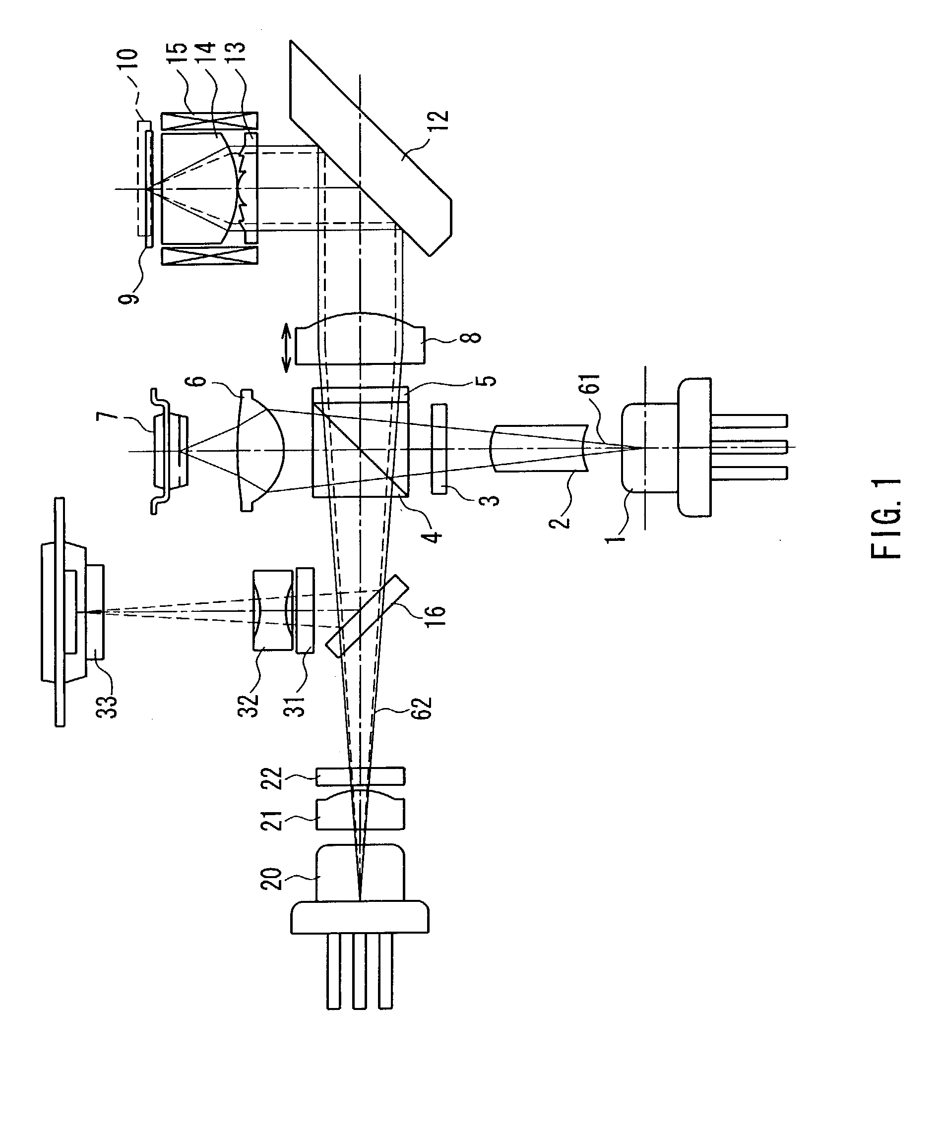
[0111]FIG. 1 is a cross-sectional view showing one exemplary configuration of an optical head according to Embodiment 1 of the present invention. In FIG. 1, reference numeral 1 denotes a blue laser light source as a first laser light source for emitting a first light beam having a wavelength λ1 (390 nm to 415 nm: in general, 405 nm is used often, so that a wavelength of 390 nm to 415 nm will be collectively referred to as “about 405 nm”); 20 denotes a red laser light source as a second laser light source for emitting a second light beam having a wavelength λ2 (630 nm to 680 nm: in general, 660 nm is used often, so that a wavelength of 630 nm to 680 nm will be collectively referred to as “about 660 nm”); 8 denotes a collimator lens; 12 denotes a rising mirror that bends an optical axis; 13 denotes a hologram (diffraction type optical element); and 14 denotes an objective lens as a refraction type lens. Herein, the hologram 13 and the objective lens 14 constitute a complex objective l...

embodiment 2

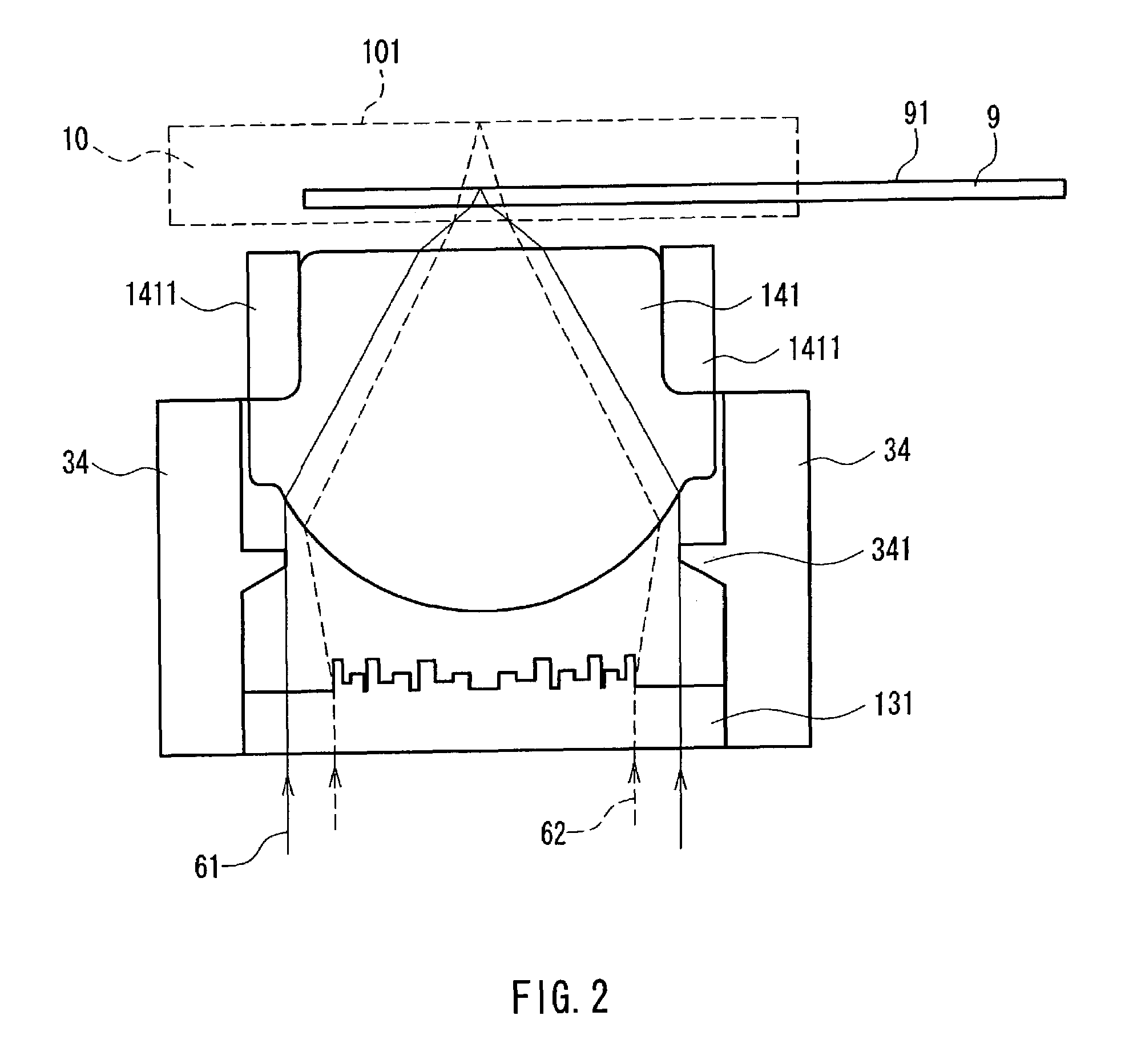
[0146]Next, Embodiment 2 of the present invention will be described. The overall configuration of an optical head according to the present embodiment is the same as that shown in FIG. 1 referred to in the description of Embodiment 1. In the present embodiment, the configuration of the hologram 13 and the objective lens 14 shown in FIG. 1 is different from that of Embodiment 1.

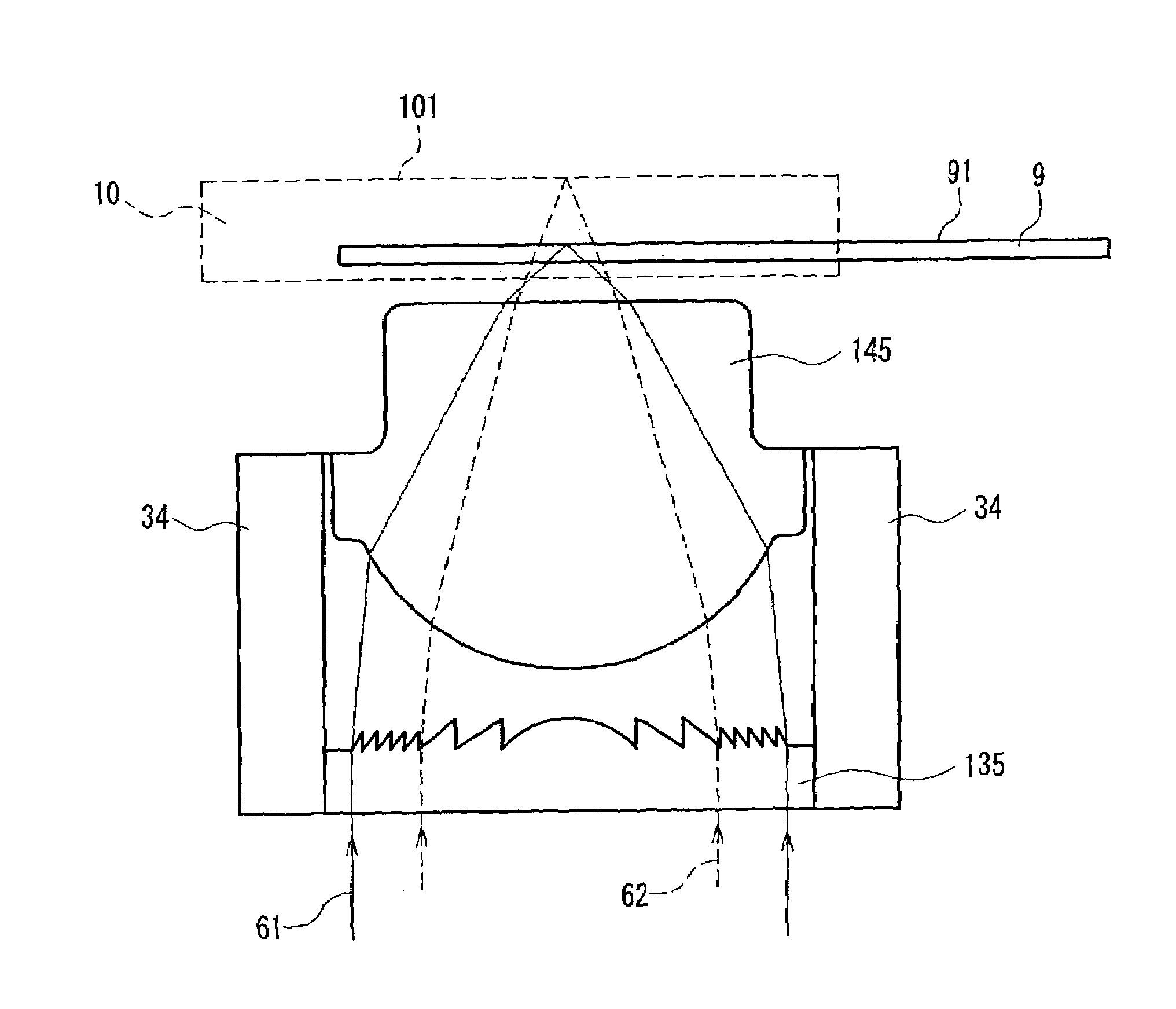
[0147]FIG. 5 is a cross-sectional view showing a specific example of a complex objective lens composed of the hologram 13 and the objective lens 14 shown in FIG. 1. In FIG. 5, reference numeral 132 denotes a hologram. The hologram 132 diffracts the blue light beam 61 with a wavelength λ1 to effect a convex lens action, and diffracts the red light beam 62 with a wavelength λ2 to effect a concave lens action, as described later. Herein, the diffraction of the lowest order that effects a convex lens action is defined as +1st-order diffraction. Then, the red light beam 62 is subjected to a concave lens action by −1...

embodiment 3

[0163]Next, Embodiment 3 of the present invention will be described. The overall configuration of an optical head according to the present embodiment is the same as that shown in FIG. 1 referred to in the description of Embodiment 1. In the present embodiment, the configuration of the hologram 13 shown in FIG. 1 is different from those of Embodiments 1 and 2.

[0164]FIGS. 8A and 8B are a plan view and a cross-sectional view showing a specific example of the hologram 13 shown in FIG. 1, respectively. In FIGS. 8A and 8B, reference numeral 133 denotes a hologram. An inner circumferential portion 133C of the hologram 133 is the same as the inner circumferential portion 132C of the hologram 132 illustrated and described in Embodiment 2. Furthermore, a grating pitch of an outer peripheral portion 133B also is the same as that of the outer peripheral portion 132B of the hologram 132 illustrated and described in Embodiment 2. However, as shown in FIG. 8B, the cross-sectional shape of a gratin...


PUM

PropertyMeasurementUnit
wavelengthaaaaaaaaaa
wavelength λ1aaaaaaaaaa

Abstract

A complex objective lens composed of a hologram and an objective lens, capable of realizing stable and high-precision compatible reproducing / recording of a BD with a base thickness of about 0.1 mm for a blue light beam (wavelength λ1) and a DVD with a base thickness of about 0.6 mm for a red light beam (wavelength λ2). In an inner circumferential portion of the hologram, a grating is formed. The hologram transmits a blue light beam as 0th-order diffracted light without diffracting it, and disperses a red light beam passing through an inner circumferential portion as +1st-order diffracted light and allows it to be condensed by an objective lens. Because of this, the focal length of the red light beam becomes longer than that of the blue light beam, whereby a working distance is enlarged.

Description

BACKGROUND OF THE INVENTION[0001]1. Field of the Invention[0002]The present invention relates to a complex objective lens in which an objective lens is combined with a hologram that is a diffraction element; an optical head for condensing light beams having a plurality of wavelengths onto an optical disk via the complex objective lens to record, reproduce, or delete information; an optical information apparatus in which the optical head is mounted; and a computer, an optical disk player, a car navigation system, an optical disk recorder and an optical disk server to which the optical information apparatus is applied.[0003]2. Description of the Related Art[0004]An optical memory technique using an optical disk having a pit-shaped pattern as a storage medium with a high density and a large capacity is being put to practical use while extending the range of uses to a digital audio disk, a video disk, a document file disk, and a data file. A function of recording / reproducing information...

Claims


Application Information

Patent Timeline
Patent Type & Authority Patents(United States)
IPC IPC(8): G02B5/32G02B3/00G11B7/1374G02B3/08G02B5/18G02B13/00G02B13/18G11B7/00G11B7/0065G11B7/125G11B7/135G11B7/1353
CPCG02B5/1866G02B5/1876G02B5/1895G02B27/4294G11B7/1275G11B7/1367G11B7/1374G11B7/13922G11B7/13925G11B7/1353G11B2007/0006G02B13/00G02B5/32
Inventor KOMMA, YOSHIAKI
Owner PANASONIC CORP
Why Eureka
Try Eureka