Method and apparatus for microarray fabrication

a microarray and fabrication method technology, applied in the field of nucleic acids, can solve the problems of incorrect fabrication of oligonucleotides, ineffective chemistries, and arising problems, and achieve the effects of reducing defect rates, and improving the fabrication of micro array devices

Inactive Publication Date: 2007-07-24
AGILENT TECH INC
View PDF21 Cites 48 Cited by
  • Summary
  • Abstract
  • Description
  • Claims
  • Application Information

AI Technical Summary

Benefits of technology

[0007]The invention provides a method and apparatus for improved fabrication of a micro array device. The micro array device is fabricated in the absence of a gas such as ozone. The apparatus of the present invention comprises a housing, a micro array substrate disposed in the housing, probes for attaching to the mic

Problems solved by technology

However, in the fabrication process a number of problems have arisen.
Problems are largely due to incorrect fabrication of oligonucleotides, ineffective chemistries, missing or extra nucleotide bases added and degradation of the oligonucleotides on the surface of the micro

Method used


Image

  • Method and apparatus for microarray fabrication
  • Method and apparatus for microarray fabrication
  • Method and apparatus for microarray fabrication

Examples


example 1

[0064]The ozone concentration in an experimental environment (array fabrication facility or enclosed housing) was measured by UV absorption at 254 nm at controlled pressure and temperature using an ozone analyzer (Advanced Pollution Instrumentation, San Diego, Calif.). When ozone levels in the housing and / or fabrication facility needed to be controlled, they were increased using an ozone generator (Zontec, Ogdensburg, N.Y.) interfaced to the ozone analyzer through a computer, or reduced by carbon filter in the intake air of the array fabrication facility or housing.

example 2

[0065]Levels of ozone that may exist in a sealed housing or array fabrication facility, were tracked over time. Levels or ozone were measured in parts per billion (ppb) for at least two days or more. Of interest were cycles or patterns correlating with cloud cover or exposure to sun. FIG. 7, shows the typical ozone levels measured in an array fabrication facility in Santa Clara county over a period of several days. Ozone levels were measured in Santa Clara County, Calif. starting on Jun. 29, 2001 at 11:00 A.M. for a period of 75 hours. It is apparent that the ozone concentration follows the diurnal cycle of the sun and that its origin derives external to the housing or array fabrication facility. Over twenty hour periods the levels of ozone were highest in the mid afternoon.

example 3

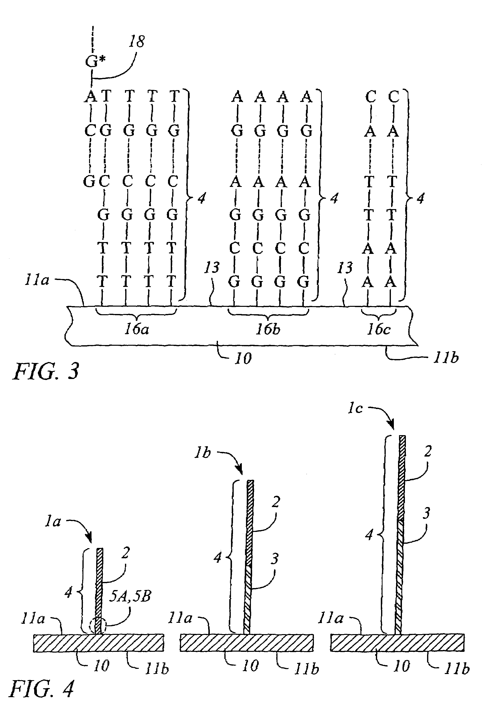
[0066]In situ DNA micro arrays were synthesized according to the techniques described previously based on phosphoramidite chemistry. Micro arrays were exposed to the ozone-controlled environment after completion of synthesis (all couplings and deprotections), as well as prior to final deprotection (after all couplings). After exposure of the micro arrays to ozone, those were hybridized and washed according to protocols described above and scanned on and Agilent scanner. Hybridization results were analyzed using Agilent software.

[0067]FIGS. 8 and 9 show the hybridization signal of a 25 mer sequence synthesized on non-hybridizing stilts of various length (25, 45 and 60 mer) following ozone exposure and hybridization with its fluorescently labeled complementary strand. The hybridization signal indicated that for the probe closest to the surface (25 mer, no stilt) the original sequence was damaged by increasing exposure time to ozone. The damage induced by ozone was also found to be dep...


PUM

PropertyMeasurementUnit
Levelaaaaaaaaaa
Defectsaaaaaaaaaa

Abstract

The invention provides a method and apparatus for micro array fabrication exclusive from the impact of a gas. A housing with a gas free chamber provides for improved micro array fabrication with a lower defect rate. The invention provides a housing that excludes a gas such as ozone to prevent interaction with probe construction or attachment. A method of fabricating a micro array in an ozone free environment is also disclosed.

Description

FIELD OF THE INVENTION[0001]The present invention relates to the field of nucleic acids and more particularly to a method for producing improved fabrication of micro array devices.BACKGROUND OF THE INVENTION[0002]Various arrays of polynucleotides (such as RNA and DNA) are known and used in genetic testing, screening and diagnostics. Arrays are defined by the regions of different biopolymers or nucleotides arranged in a predetermined configuration on a substrate. Most importantly, the arrays when exposed to a population of analytes will exhibit a pattern indicative of the presence of the various components separated spatially. Array binding patterns of polynucleotides and / or peptides can be detected by using a variety of suitable target labels. Once bound to the array, these target labels can then be quantified and observed and the overall pattern on the array determined.[0003]A number of methods have been designed for manufacturing micro arrays. DNA micro arrays are particularly use...

Claims


Application Information

Patent Timeline
IPC IPC(8): A61L33/00B05D3/00
CPCB01J19/0046B82Y30/00B01J2219/00378B01J2219/00387B01J2219/00497B01J2219/00527B01J2219/00547B01J2219/00585B01J2219/00596B01J2219/00605B01J2219/0061B01J2219/00612B01J2219/00626B01J2219/00637B01J2219/00659B01J2219/00662B01J2219/00675B01J2219/00677B01J2219/00722B01J2219/00725B01J2219/00731
Inventor LEPROUST, ERIC M.REDDY, LALITHAPERBOST, MICHEL G M
Owner AGILENT TECH INC
Why Eureka
Try Eureka