Radiometer measurement linearization system and method

a linearization system and radiation measurement technology, applied in the field of radiation detectors, can solve the problems of poor image quality, limited sensitivity of existing radiometer designs, and limited to about 1 deg k, so as to reduce calibration requirements, improve the dynamic range of input signals, and eliminate sensitivity to gain variations.

Active Publication Date: 2007-07-31
REVEAL IMAGING
View PDF5 Cites 28 Cited by
  • Summary
  • Abstract
  • Description
  • Claims
  • Application Information

AI Technical Summary

Benefits of technology

[0011]A radiometer system in accordance with one non-limiting example of the present example includes a dual channel, quadrature hybrid amplifier circuit that receives an antenna signal and a known reference signal. A detector circuit receives a signal from the quadrature hybrid amplifier circuit to equalize gain in two parallel gain stages and detects the signals to form a detected output. A log ratio amplifier receives and linearizes the detected output for eliminating sensitivity to gain variations, improving dynamic range of the input signal, and reducing calibration requirements. An integrator circuit receives a signal from the log ratio amplifier and sums the signal over an observation period. A digital acquisition and processing circuit can receive a signal from the integrator circuit for further radiometer processing.

Problems solved by technology

The sensitivity of existing radiometer designs, however, has been limited to about 1 deg K., resulting in poor images.
The sensitivity of radiometer measurements are also often limited by random gain fluctuations in the RF front end, low frequency noise (1 / f), and bias in the detector circuits.
Many of these proposals have not yielded a solution that will allow MMW radiometers to be commercially viable.
Also, the high cost of MMW RF receivers has limited the number of channels in the radiometer to a low number, resulting in a requirement to scan both azimuth and elevation to create an image.
A challenging aspect of radiometer sensing is the ability to maintain stability over time and temperature.
When multiple channel radiometer systems are used, channel-to-channel stability is a challenge.
This technique, however, is costly and requires hours of testing per unit.
It is also a roadblock to proliferation of radiometer sensors for commercial applications.

Method used


Image

  • Radiometer measurement linearization system and method
  • Radiometer measurement linearization system and method
  • Radiometer measurement linearization system and method

Examples


Embodiment Construction

[0030]The present invention will now be described more fully hereinafter with reference to the accompanying drawings, in which preferred embodiments of the invention are shown. This invention may, however, be embodied in many different forms and should not be construed as limited to the embodiments set forth herein. Rather, these embodiments are provided so that this disclosure will be thorough and complete, and will fully convey the scope of the invention to those skilled in the art. Like numbers refer to like elements throughout.

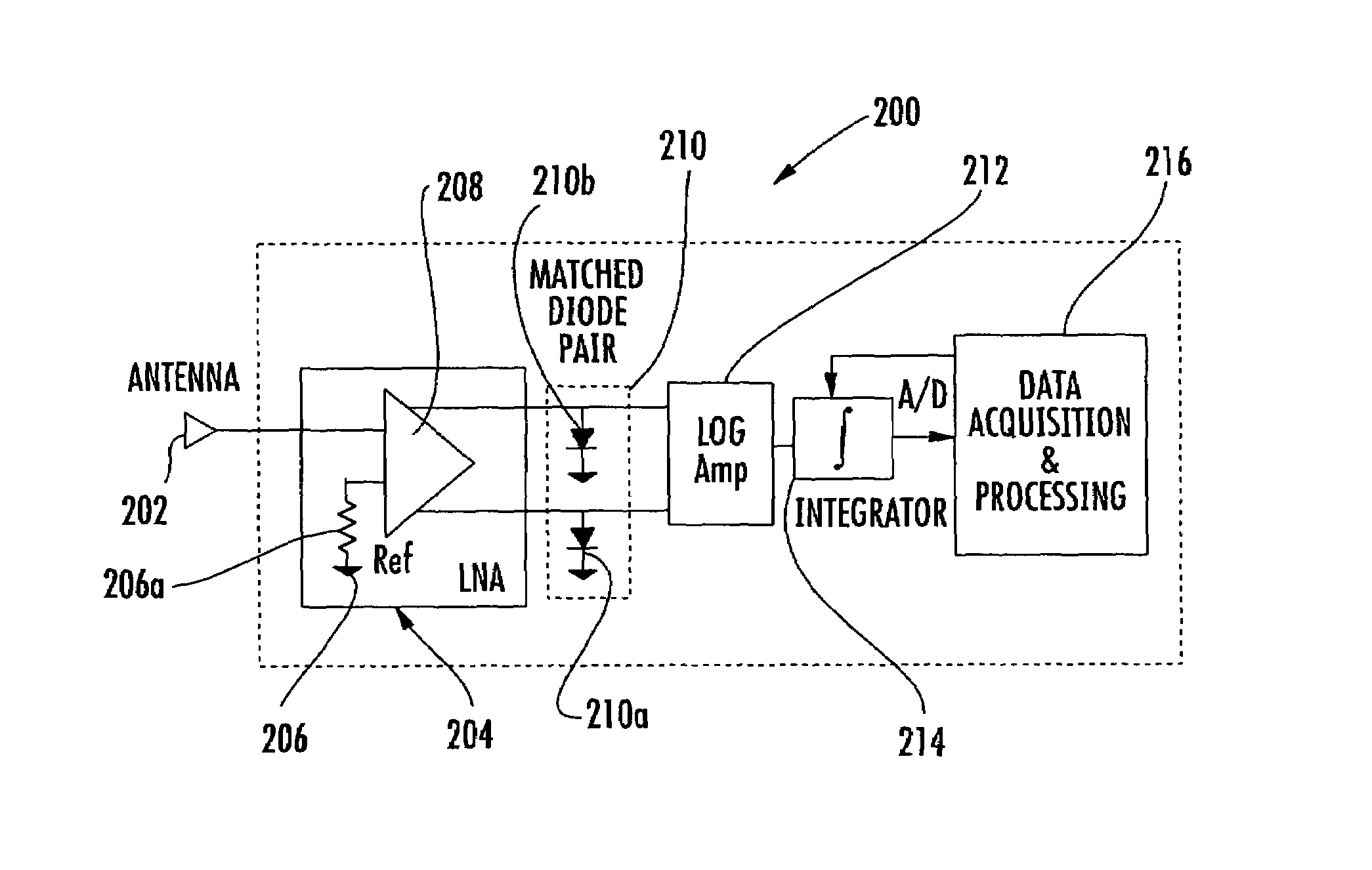
[0031]As known to those skilled in the arts, absorbance and transmittance measurements are typically performed with a light source. Transmittance is the ratio of light intensity before and after it enters a medium. Absorbance is the logarithm of transmittance. Applying these two principles to a radiometer system in accordance with one non-limiting example of the present invention can result in robust radiometeric sensing. Similar to optics, transmittance i...


PUM


Abstract

A radiometer system includes a dual channel, quadrature hybrid amplifier circuit that receives an antenna signal and a known reference signal to equalize gain in two parallel gain stages. A detector circuit receives a signal from the quadrature hybrid amplifier circuit and detects the signals to form a detected output for eliminating sensitivity to gain variations, improving dynamic range of the input signal, and reducing calibration requirements. A log ratio amplifier receives and linearizes the detected output. An integrator circuit receives a signal from the log ratio amplifier and sums the signal over an observation.

Description

FIELD OF THE INVENTION[0001]This application relates to the field of radiometers, and more particularly, this invention relates to radiometers having improved sensor stability.BACKGROUND OF THE INVENTION[0002]Since radio waves may be considered infrared radiation of long wave, a hot body would be expected to radiate microwave energy thermally. In order to be a good radiator of microwave energy, a body should be a good absorber. An adequate thermal radiator is a “black body.” The amount of radiation emitted in the Millimeter Wave (MMW) range is about 108 times smaller than the amount emitted in the infrared range. Current MMW receivers, however, typically have at least 105 times better noise performance than infrared detectors, and with some temperature contrast, the remaining 103 may be recovered. This makes passive MMW imaging comparable in performance with current infrared systems, making MMW radiometers a popular choice for sensing thermal radiation. MMW radiometers have been use...

Claims


Application Information

Patent Timeline
Patent Type & Authority Patents(United States)
IPC IPC(8): G01S3/02
CPCG01J5/522G01K11/006G01J5/53
Inventor AMMAR, DANNY F.
Owner REVEAL IMAGING
Why Eureka
Try Eureka