Sigma-delta modulator

Active Publication Date: 2007-07-31
DIALOG SEMICONDUCTOR GMBH
View PDF10 Cites 27 Cited by
  • Summary
  • Abstract
  • Description
  • Claims
  • Application Information

AI Technical Summary

Benefits of technology

[0013]A principal object of the present invention is to achieve methods an...

Problems solved by technology

It is a challenge for the designers of sigma delta modulators to achieve low noise and low offse...

Method used


Image

  • Sigma-delta modulator
  • Sigma-delta modulator
  • Sigma-delta modulator

Examples


Embodiment Construction

[0034]The preferred embodiments disclose methods and circuits for continuous time sigma-delta modulators. In a preferred embodiment such a delta-sigma modulator is used for battery management. The principle of the methods and circuits invented can be used also for many continuous-time modulators, because it replaces the necessity for return-to-zero code (RZ) and hence improves ISI and distortion. The disadvantage of RZ code is degrading of frequency characteristics.

[0035]The preferred embodiments have been implemented in an integrated circuit (IC) using CMOS-technology; other semiconductor technologies are also possible.

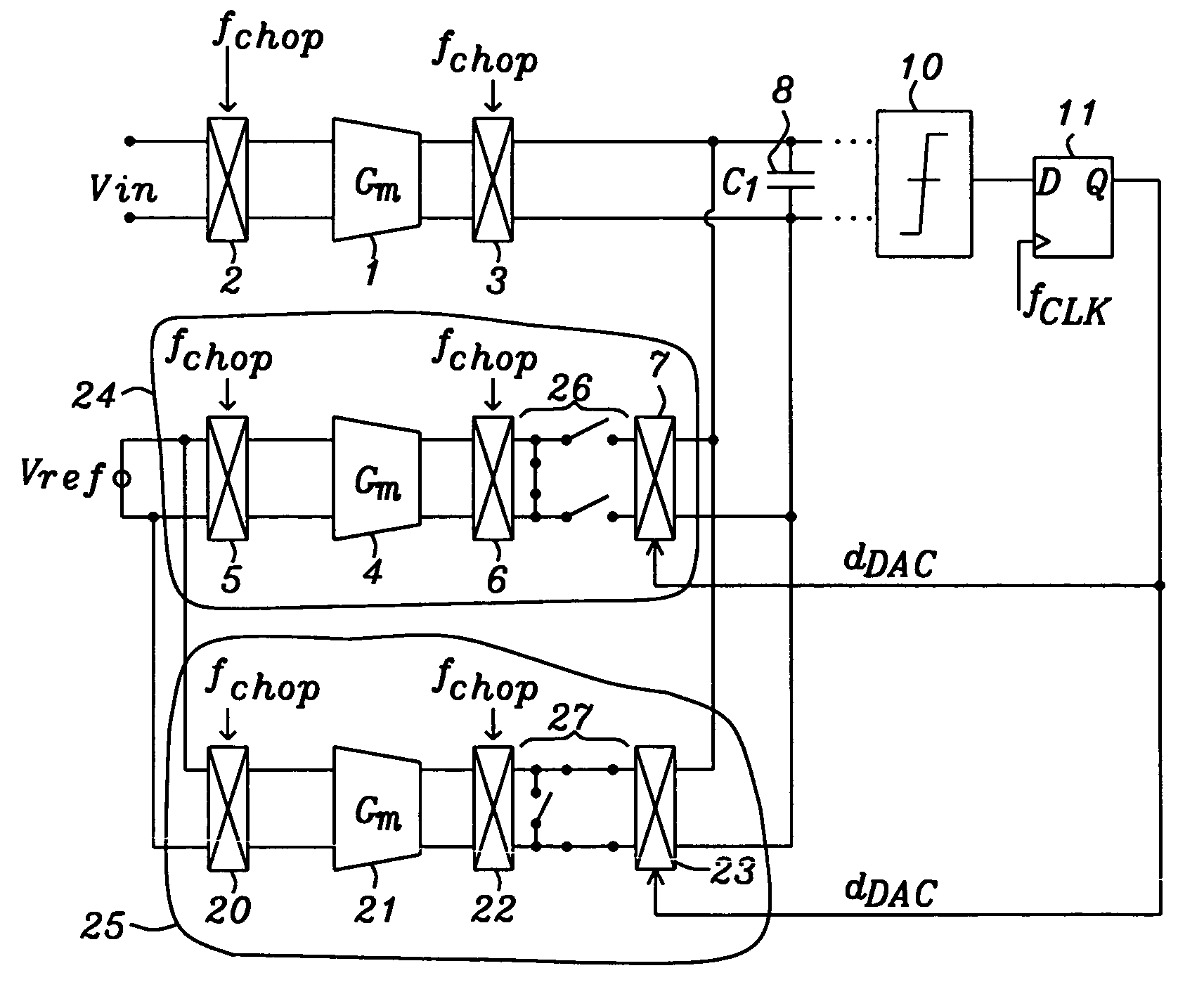
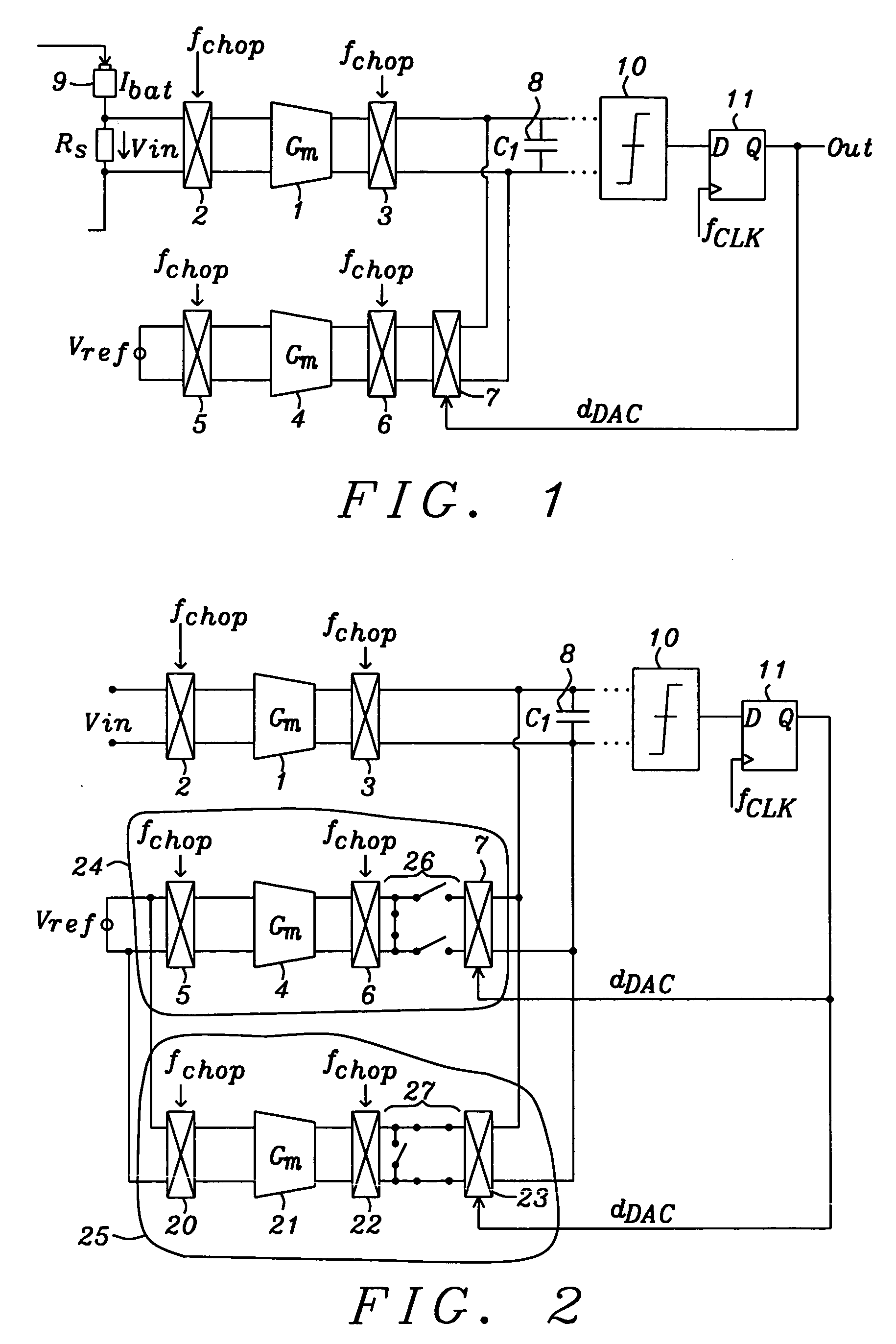
[0036]FIG. 1 shows a novel feature of a sigma-delta modulator used for battery management purposes as a non-limiting example. A first stage of a sigma-delta modulator of FIG. 1 comprises a first differential Gm integrator 1, a chopping multiplexer 2 alternates with the chopping frequency fchop the polarity of the input voltage Vin of the differential Gm integrator 1....


PUM


Abstract

Circuits and methods to achieve a low-noise and low offset continuous sigma-delta modulator used e.g. for battery management are disclosed. Continuous integration of input is enabled by special switching principle of three parallel integrators. Precharging of integrator output in so called pre-run mode minimizes integrator leakage and non-ideal effects by connecting a Gm in pre-run mode either to input voltage or to a reference voltage depending this Gm is being used in a following clock period. Parasitic effects due to switching at first integration capacitor are minimized by using buffer amplifiers tracking the voltage on integration capacitors.

Description

BACKGROUND OF THE INVENTION[0001](1) Field of the Invention[0002]This invention relates generally to analog-to digital converters and relates more particularly to low-noise and low offset continuous-time Sigma-Delta Modulators. The principle can be used also for many continuous-time modulators, because it replaces the necessity for return-to-zero code (RZ) and hence improves ISI and distortion. The disadvantage of RZ code is degrading of frequency characteristics.[0003](2) Description of the Prior Art[0004]Oversampling modulation techniques have become popular today for high-resolution analog signal processing applications such as data conversion and signal generation. The major reason for their popularity comes about because their implementations rely less on the matching of analog components and amplifier gains, and more on digital signal processing. This is advantageous today as submicron VLSI technologies are more amenable for integrating complex digital signal processing operat...

Claims


Application Information

Patent Timeline
IPC IPC(8): H03M3/00
CPCH03K17/0416H03M3/34H03M3/464H03M3/43H03M3/456
Inventor KILLAT, DIRKADLER, ANDREAS
Owner DIALOG SEMICONDUCTOR GMBH
Why Eureka
Try Eureka