
Wood chip flinger and method of densely packing wood chips with large angle output

Inactive Publication Date: 2007-08-07
BAILEY CONSULTING
View PDF17 Cites 17 Cited by
  • Summary
  • Abstract
  • Description
  • Claims
  • Application Information

AI Technical Summary

Benefits of technology

[0007]A wood chip handling device of the present invention allows wood chips to be packed (or, synonymously “stacked”) with a density greater than that achieved using conventional free-fall techniques. Preferably, the device packs the wood chips at a density that is at least 20% more than that achieved with the conventional free-fall techniques.

Problems solved by technology

One major factor in the cost of wood chips for paper making is the cost of transporting the wood chips from the chip manufacturing site to the paper mill.
Typically, the transportation costs are based primarily on the number of containers used to ship a given load of wood chips.
For instance, the storage of wood chips on site, such as at a pulp mill, consumes space.

Method used


Image

  • Wood chip flinger and method of densely packing wood chips with large angle output
  • Wood chip flinger and method of densely packing wood chips with large angle output
  • Wood chip flinger and method of densely packing wood chips with large angle output

Examples


Embodiment Construction

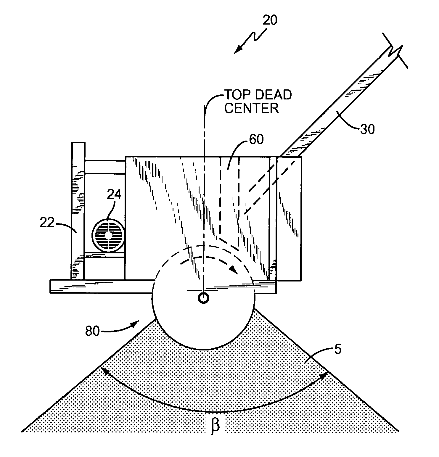
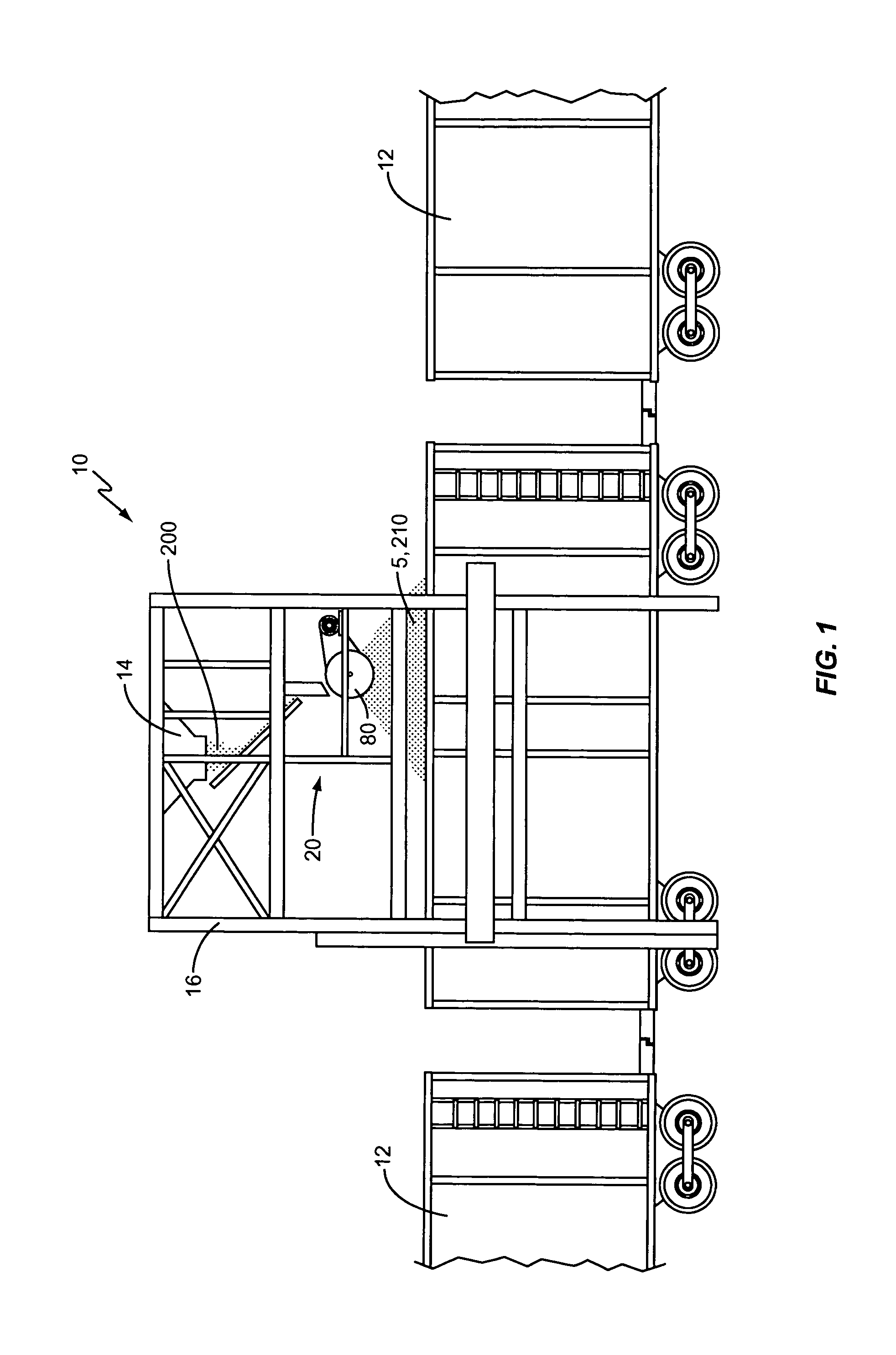
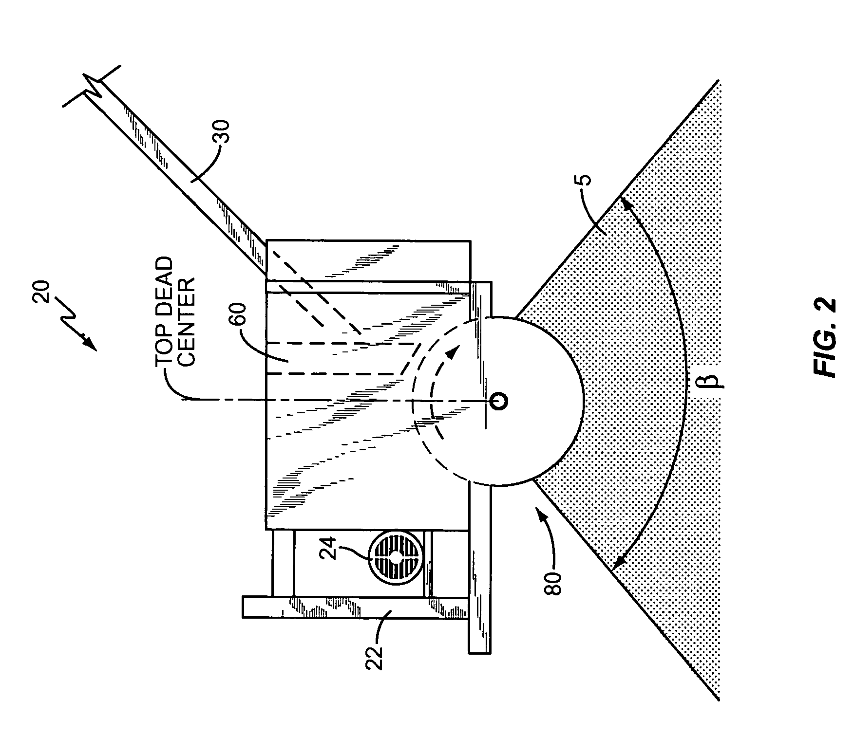
[0015]In order to provide a better understanding of the present invention, one embodiment of the wood chip handling device according to the present invention is shown in FIG. 1 in the context of a wood chip loading station 10 for filling railcars 12. The wood chip handling device, generally indicated at 20, is shown installed in a tower structure 16 that extends above a rail line with a railcar 12 thereon. Wood chips 5 are fed to the handling device 20 in the tower 16 by any suitable means, such as by conventional conveyor system 14 (only the output funnel of which is shown for clarity), or alternatively via a pneumatic means into a cyclone, or by other like means known in the art. While the input feed system (e.g., conveyor system 14) is shown with only one output, it should be understood that the input feed system may have multiple outputs, such as in a so-called “pants leg” inverted “Y” system known in the art, advantageously with a handling device 20 at each output. The handling...


PUM

PropertyMeasurementUnit
Angleaaaaaaaaaa
Angleaaaaaaaaaa
Angleaaaaaaaaaa

Abstract

A handling device packs wood chips with a density greater than that achieved using conventional free-fall techniques by ≧20%-35%. The device includes a drum rotating about a generally horizontal axis that includes a plurality of outwardly extending blades that act to fling the wood chips so as to land with a substantially uniform orientation. The blades may comprise a leading face with at least a first face section that extends in a first direction and at least a second face section extending at a forward angle relative to the first section. The first direction may be generally normal to the drum core's peripheral surface. The output from the drum, when an input stream of wood chips is fed to the drum, covers an arc of at least 90°, typically in the range of 90°-120° and generally downwardly facing, when viewed from the side along the axis.

Description

[0001]This application is a continuation-in-part application of U.S. patent application Ser. No. 10 / 241,725, filed Sep. 11, 2002, now U.S. Pat. No. 6,811,020, and a continuation-in-part of U.S. patent application Ser. No. 10 / 465,182, filed Jun. 19, 2003, now abandoned, the disclosures of which are incorporated herein by reference.BACKGROUND OF THE INVENTION[0002]The present invention relates generally to the field of wood chip processing, and more particularly to a machine and associated method for dense packing of wood chips for storage, transport, or further processing.[0003]One major factor in the cost of wood chips for paper making is the cost of transporting the wood chips from the chip manufacturing site to the paper mill. The wood chips are typically transported in rail cars, but may also be transported in barges, trailers, or the like. Typically, the transportation costs are based primarily on the number of containers used to ship a given load of wood chips. As more densely ...

Claims


Application Information

Patent Timeline
IPC IPC(8): B65G65/30B65B1/20B65B37/12
CPCB65B1/20B65B37/12
Inventor BAILEY, KENNETH F.
Owner BAILEY CONSULTING
Learn More