Offset adjusting circuit for optical disc and offset adjusting method

Inactive Publication Date: 2007-08-14
SEMICON COMPONENTS IND LLC
View PDF3 Cites 8 Cited by
  • Summary
  • Abstract
  • Description
  • Claims
  • Application Information

AI Technical Summary

Benefits of technology

[0016]Hence, by varying the control voltage of the offset-adjustment differential operational amplifier to which an output signal of the optical pickup is input, the offset of the output signal is adjusted. Thus, first, the offset of the output signal that originates from the optical pickup can be adjusted. In addition, the offset that originates from the offset-adjustment differential operational amplifier and the analog processing system can be adjusted together therewith. Therefore, the output signal of the offset-adjustment differential operational amplifier is a signal having the offset that originates from the upstream processing system including the optical pickup adjusted. As a result, also in the downstream processing system, which performs signal processing based on the output signal having the offset adjusted, such as a circuit generating error signals, e.g., the tracking error signal and the focus error signal, the output signal of the offset-adjustment differential operational amplifier can be made to fall within the dynamic range of the A / D converter and the like. Therefore, the dynamic range of each circuit that processes the signal having the offset adjusted can be effectively utilized.
[0017]Hence, the offset that originates from the upstream processing system including the optical pickup can be adjusted. As a result, accuracy degradation such as waveform distortion can be prevented in signal processing such as generating an error signal, and thereby a highly accurate error signal can be obtained. Thus, accuracy degradation in servo control based on the error signal can be prevented.

Problems solved by technology

Accordingly, if variations occur in the intensity of the reflected light because the specifications or the like of the optical pickup are different or the type of optical disc is different, the output signals from the optical pickup themselves cannot be accurately adjusted in terms of offsets.
As a result, the error signals are generated based on the output signals whose offsets have not been accurately adjusted.
Hence, at the stage where a differential operational amplifier takes the difference in intensity between two output signals of the optical pickup to generate an error signal, due to insufficient adjustment of the offset, the two output signals deviate from the dynamic range of a processing system including the differential operational amplifier, so that the waveforms thereof become distorted.
Thus, an appropriate error signal cannot be generated, thereby causing the degradation of servo control based on the error signal.

Method used


Image

  • Offset adjusting circuit for optical disc and offset adjusting method
  • Offset adjusting circuit for optical disc and offset adjusting method
  • Offset adjusting circuit for optical disc and offset adjusting method

Examples


Embodiment Construction

[0026]At least the following matters will be made clear by the explanation in the present specification and the description of the accompanying drawings.

[0027]====Entire Outline====

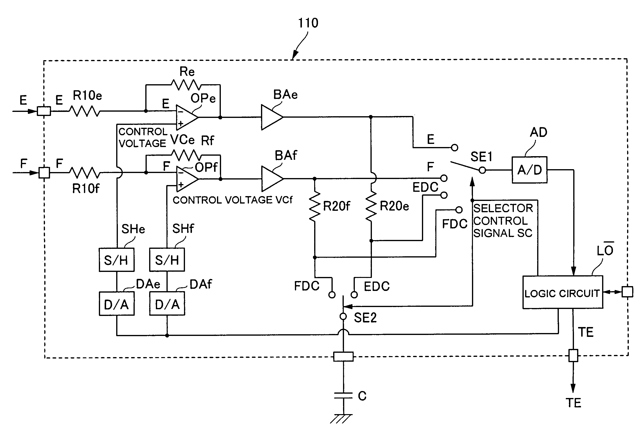
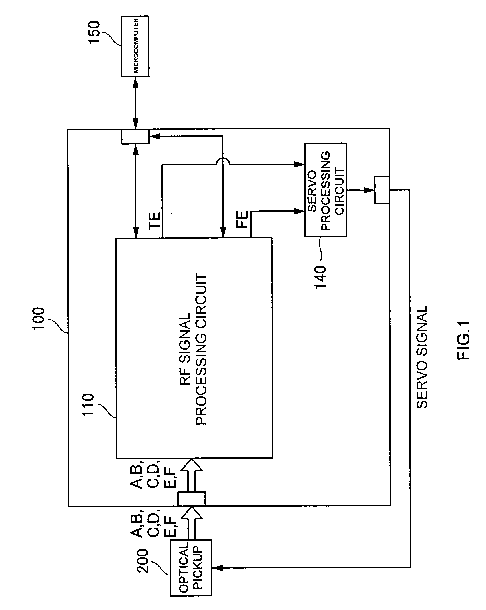
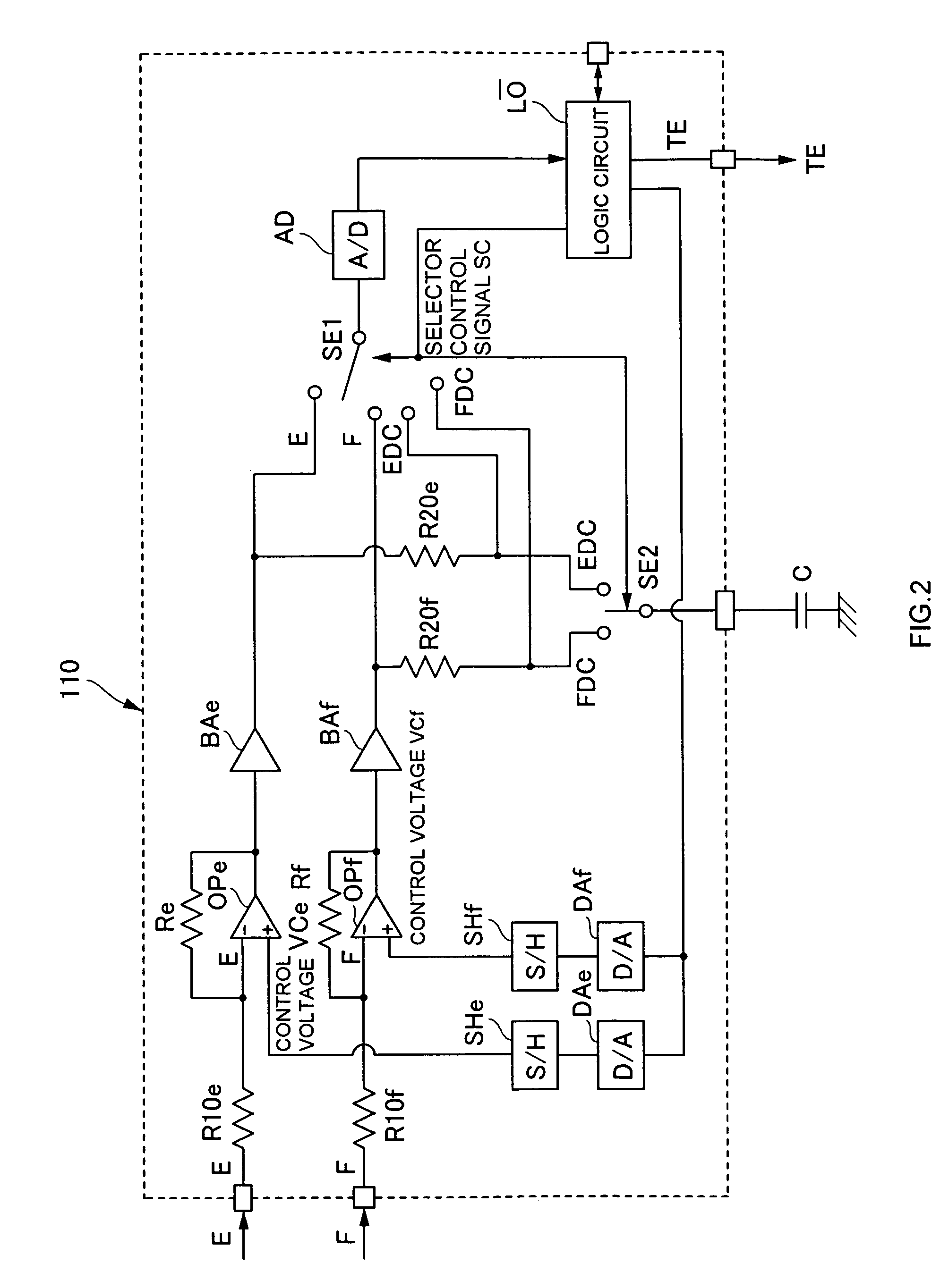
[0028]As shown in FIG. 1, an optical disc error signal generating circuit (servo signal processing apparatus) 100 is applied, for example, to the above-mentioned optical disc apparatus as shown in FIG. 5, and generates the tracking error signal TE and the focus error signal FE adjusted to remove or reduce DC offsets (direct current component offsets of the signals) based on a group of signals from the optical pickup 200. Note that the group of signals from the optical pickup 200 includes A to F signals as known well. This optical disc error signal generating circuit 100 is constituted by a one-chip-type integrated circuit. Alternatively, this integrated circuit can be produced with a CMOS process as a part of an optical disc playback signal processing LSI. The optical disc error signal generating circuit ...


PUM


Abstract

An offset adjusting circuit for an optical disc comprises an offset-adjustment differential operational amplifier having an input terminal to which an output signal of an optical pickup is input and the other input terminal to which a control voltage is applied, an A / D converter that outputs a digital signal based on an output signal of the offset-adjustment differential operational amplifier, and a control voltage adjuster that varies the control voltage applied to the offset-adjustment differential operational amplifier based on the digital signal so as to remove an offset.

Description

NOTICE OF COPYRIGHTS AND TRADE DRESS[0001]A portion of the disclosure of this patent document contains material which is subject to copyright protection. This patent document may show and / or describe matter which is or may become trade dress of the owner. The copyright and trade dress owner has no objection to the facsimile reproduction by any one of the patent disclosure as it appears in the Patent and Trademark Office patent files or records, but otherwise reserves all copyright and trade dress rights whatsoever.RELATED APPLICATION INFORMATION[0002]This application claims priority upon Japanese Patent Application No. 2003-144037 filed on May 21, 2003, which is herein incorporated by reference.BACKGROUND OF THE INVENTION[0003]1. Field of the Invention[0004]The present invention relates to an offset adjusting circuit for an optical disc and an offset adjusting method.[0005]2. Description of the Related Art[0006]Generally, in an optical disc playback (and recording) apparatus (herein...

Claims


Application Information

Patent Timeline
IPC IPC(8): G11B7/00G11B7/09G11B7/095
CPCG11B7/094A47J36/04A47J37/067
Inventor SASAKI, HIDEAKI
Owner SEMICON COMPONENTS IND LLC
Why Eureka
Try Eureka