Microelectromechanical slow-wave phase shifter device and method

a phase shifter and microelectromechanical technology, applied in waveguides, delay lines, electrical equipment, etc., can solve the problems of physical limitation of the performance achievable with rf mems ttd devices, large phased array radar systems can cost millions of dollars, and restrict the achievable per unit length

a phase shifter and microelectromechanical technology, applied in waveguides, delay lines, electrical equipment, etc., can solve the problems of physical limitation of the performance achievable with rf mems ttd devices, large phased array radar systems can cost millions of dollars, and restrict the achievable per unit length

US7259641B1Inactive Publication Date: 2007-08-21UNIV OF SOUTH FLORIDA

Image

  • Microelectromechanical slow-wave phase shifter device and method
  • Microelectromechanical slow-wave phase shifter device and method
  • Microelectromechanical slow-wave phase shifter device and method

Examples


Embodiment Construction

[0036]In the following detailed description of the preferred embodiments, reference is made to the accompanying drawings, which form a part hereof, and within which are shown by way of illustration specific embodiments by which the invention may be practiced. It is to be understood that other embodiments may be utilized and structural changes may be made without departing from the scope of the invention.

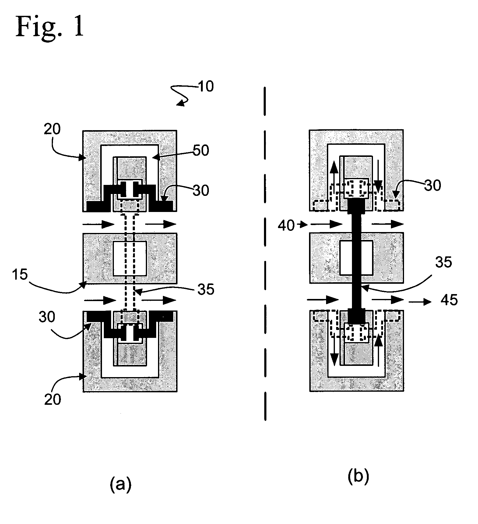
[0037]The differential phase shift between the up- and down-states of a DMTL with capacitive-loading is accompanied by a change in the effective characteristic impedance in each state. Using the quasi-TEM assumption, the relationship between phase shift for a DMTL of length L and characteristic impedance is derived as shown below in Equation 1. Assuming a reference impedance of 50Ω, Zup and Zdn need to be approximately 55Ω and 45.4Ω, respectively, in order to maintain RL greater than 20 dB. The resulting Δφ per unit length is 17.8° / mm at 50 GHz. Achieving this small variation in the ...


PUM

PropertyMeasurementUnit
impedanceaaaaaaaaaa
impedanceaaaaaaaaaa
impedanceaaaaaaaaaa

Abstract

The present invention provides a method and apparatus for a monolithic device utilizing cascaded, switchable slow-wave CPW sections that are integrated along the length of a planar transmission line. The purpose of the switchable slow-wave CPW sections elements is to enable control of the propagation constant along the transmission line while maintaining a quasi-constant characteristic impedance. The device can be used to produce true time delay phase shifting components in which large amounts of time delay can be achieved without significant variation in the effective characteristic impedance of the transmission line, and thus also the input / output return loss of the component. Additionally, for a particular value of return loss, greater time delay per unit length can be achieved in comparison to tunable capacitance-only delay components.

Description

CROSS-REFERENCE TO RELATED DISCLOSURE[0001]This application claims priority to provisional application entitled: “True Time Delay Phase Shifting Method and Apparatus with Slow-Wave Elements,” filed Feb. 27, 2004 by the present inventors and bearing application No. 60 / 521,146.GOVERNMENT SUPPORT[0002]This invention was developed under support from the National Science Foundation under grant / contract number 2106-301-LO; accordingly the U.S. government has certain rights in the invention.BACKGROUND OF INVENTION[0003]A true time delay (TTD) phase shifter is a component used in microwave and millimeter wave radar and communications systems to control the time delay imposed upon a signal along a particular signal path within a system. The most common use of TTD components is within phased array radars, where it is possible that thousands of TTD components may be necessary and would be connected to each antenna element within a large array of such elements. In such an example the TTD compon...

Claims


Application Information

Patent Timeline
21 Aug 2007
Publication
US7259641B1
IPC
H01P1/18
CPC
H01P1/184; Y10T29/49105; Y10T29/49002; Y10T29/49016
Inventors
WELLER, THOMAS; LAKSHMINARAYANAN, BALAJI