Flash curing in selective deposition modeling

a selective deposition and curing technology, applied in the field of solid deposition modeling, can solve the problems of reducing the efficiency of curing in these materials, unable to effectively initiate curing of free radicals, and unable to effectively inhibit oxygen in the atmosphere, so as to achieve the effect of substantially reducing power consumption and heat generation

Inactive Publication Date: 2007-09-18
3D SYST INC
View PDF35 Cites 46 Cited by
  • Summary
  • Abstract
  • Description
  • Claims
  • Application Information

AI Technical Summary

Benefits of technology

[0017]It is an advantage of the present invention that both power consumption and heat generation are substantially reduced when curing a material by exposure to a planar flash of radiation.
[0018]It is another advantage of the present invention that oxygen inhibition is overcome when curing thin layers of curable materials by exposure to a broad planar flash of radiation.
[0019]These and other aspects, features, and advantages are achieved / attained in the method and apparatus of the present invention. The method of the present invention comprises generating computer data corresponding to layers of the object, dispensing a curable material in the build environment according to the computer data to form layers of the object, supporting the dispensed material in the build environment; and exposing the dispensed material to at least one planar flash of radiation to cure the dispensed material. The planar flash comprises a plurality of radiation emitting pulses that initiate curing of the dispensed material.
[0020]The selective deposition modeling apparatus of the present invention comprises a support means, dispensing means, and flash exposure means. The support means is affixed to the apparatus for supporting the three-dimensional object in the build environment. The dispensing means is affixed to the apparatus and in communication with the support means for dispensing the curable material in the build environment according to the computer data to form the layers of the three-dimensional object. The flash exposure means is affixed to the apparatus and in communication with the support means for exposing the dispensed material in the build environment to at least one planar flash of radiation. The planar flash comprises a plurality of radiation emitting pulses that initiate curing of the dispensed material.
[0021]A flash curing system of the present invention comprises at least one flash lamp, a pulse-forming network, trigger, and power supply. The flash lamp produces at least one planar flash comprising a plurality of radiation emitting pulses. The pulse-forming network is operably connected to the flash lamp for providing the excitation energy to the flash lamp to generate the plurality of radiation emitting pulses. The excitation energy for each radiation emitting pulse is between about 1 and about 15 joules at a direct current voltage of about 2250 volts or less. The trigger is operably connected between said flash lamp and the pulse-forming network for initiating delivery of the excitation energy from the pulse-forming network to the flash lamp to generate each pulse. The power supply is operably connected to the pulse-forming network for initially supplying the excitation energy and re-supplying the excitation energy to the pulse-forming network prior to each pulse. Desirably the power supply consumes less than about 1000 watts of power, more preferably less than about 800 watts, even more preferably less than about 600 watts, and most preferably less than about 500 watts.

Problems solved by technology

However, developing a flood UV exposure system that effectively initiates curing in these materials proven problematic.
The region is so small the free radicals lack the opportunity to react with the oxygen in the atmosphere.
However, oxygen inhibition is a significant problem in SDM applications where a broad planar flood exposure is desired to initiate the curing process.
Although this phenomena can be overcome by submersing the SDM build environment in an inert gas, providing such a system only adds additional complexity and expense to an SDM system that is to be avoided.
Undesirably, the high levels of heat generated by these lamps pose significant problems in SDM.
Undesirably, if these continuously emitting lamps are to be used, the high levels of heat they generate may require special active cooling systems to be incorporated into the system to make the system operable.
Further, experiments with continuous UV emitting lamps not only demonstrated that they consume significant amounts of power, typically around 1500 Watts, but also that many curable formulations would not cure due to oxygen inhibition.
Although these commercially available systems are capable of overcoming the problem of oxygen inhibition, they are generally not practical for use in SDM.
For example, commercially available power supplies for use in charging these pulse systems have large input power requirements, often around 40 kilowatts or more.
Thus, these flash curing systems operate at power levels that are too high to be useful in SDM systems.
For SDM applications a lower power consumption flash curing system is needed, but not available.

Method used


Image

  • Flash curing in selective deposition modeling
  • Flash curing in selective deposition modeling
  • Flash curing in selective deposition modeling

Examples


Embodiment Construction

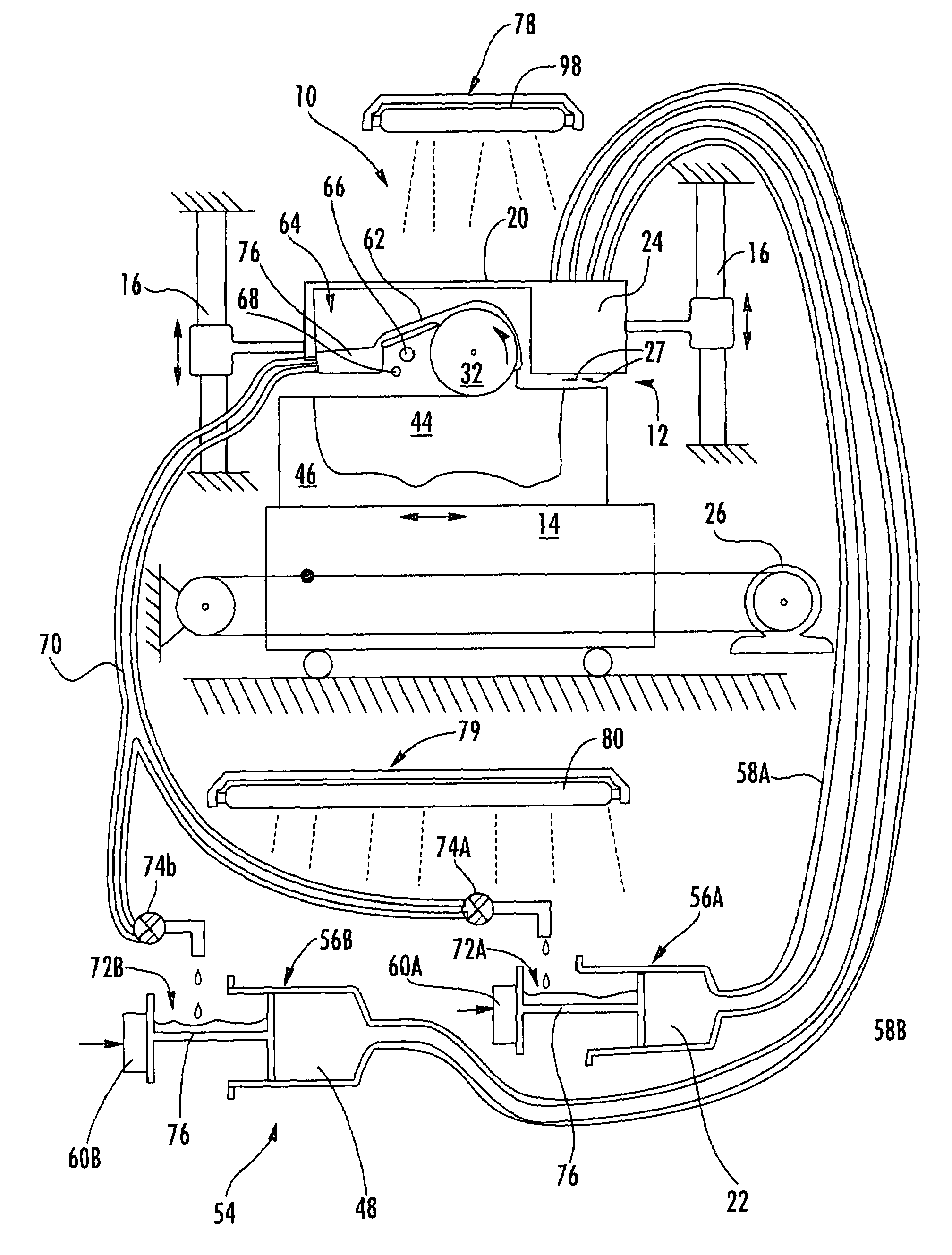
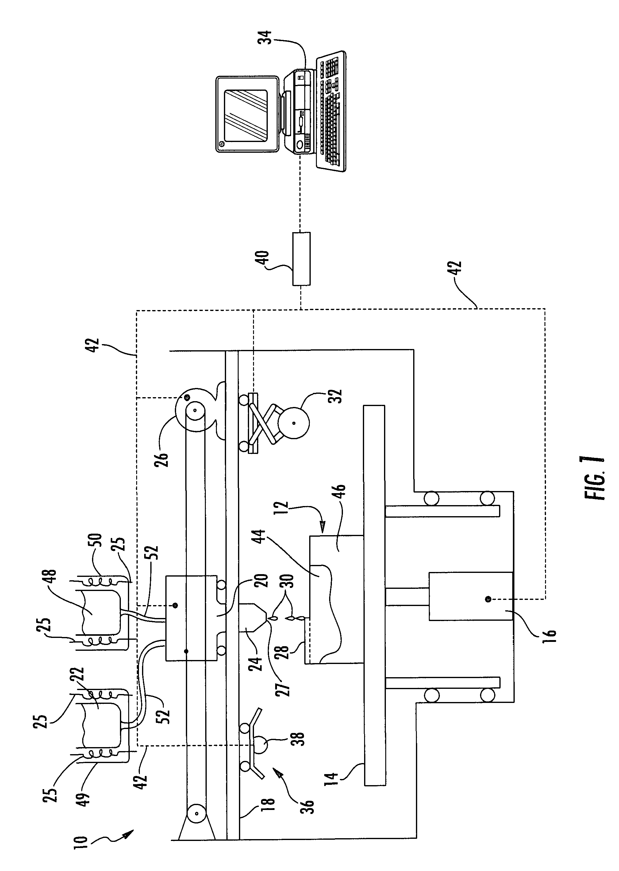
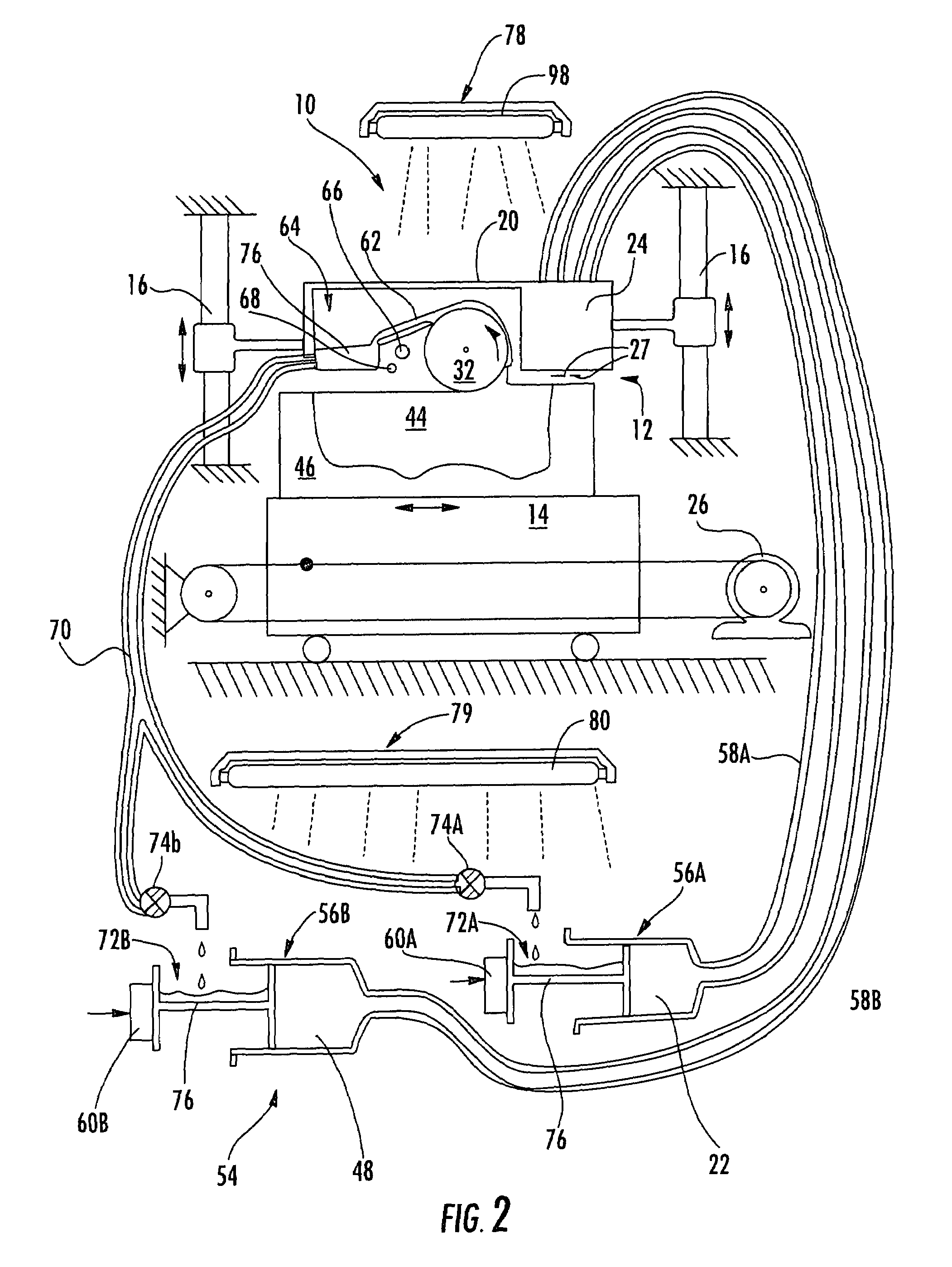
[0031]While the flash curing system of the present invention is applicable to all SFF techniques that could utilize in using a planar flash curing system to cure a build material, the invention will be described with respect to an SDM technique utilizing an ink jet print head dispensing a ultraviolet radiation curable phase change material. However, it is to be appreciated that the present invention flash curing system can be implemented with any SFF technique utilizing a wide variety of curable materials. For example, the curable material can be cured by exposure to radiation having wavelengths other than in the ultraviolet band of the spectrum, if desired.

[0032]As used herein, the term “a flowable state” of a build material is a state wherein the material is unable to resist shear stresses that are induced by a dispensing device, such as those induced by an ink jet print head when dispensing the material, causing the material to move or flow. Preferably, the flowable state of the ...


PUM

PropertyMeasurementUnit
average power consumptionaaaaaaaaaa
wavelengthsaaaaaaaaaa
areaaaaaaaaaaa

Abstract

A flash curing system for solid freeform fabrication which generates a plurality of radiation emitting pulses that forms a planar flash. The planar flash initiates curing of a curable material dispensed by a solid freeform fabrication apparatus. The radiation emitting pulses have a high peak power value that releases a sufficient quantity of free radicals from the photoinitiator to initiate curing and overcome the problem of oxygen inhibition. Substantially less power is consumed and less heat generated by the flash curing system compared to conventional continuous emission curing systems.

Description

BACKGROUND OF THE INVENTION[0001]1. Field of the Invention[0002]The invention relates in general to solid deposition modeling, and in particular to a method and apparatus for providing a planar flash to cure layers of a build material to form a three-dimensional object. The flash curing system substantially eliminates the problem of oxygen inhibition encountered when attempting to cure thin layers exposed to air.[0003]2. Description of the Prior Art[0004]Recently, several new technologies have been developed for the rapid creation of models, prototypes, and parts for limited run manufacturing. These new technologies are generally called Solid Freeform Fabrication techniques, and are herein referred to as “SFF.” Some SFF techniques include stereolithography, selective deposition modeling, laminated object manufacturing, selective phase area deposition, multi-phase jet solidification, ballistic particle manufacturing, fused deposition modeling, particle deposition, laser sintering, an...

Claims


Application Information

Patent Timeline
Patent Type & Authority Patents(United States)
IPC IPC(8): B29C35/08B29C67/00G03F7/00
CPCB29C35/0805B29C67/0059G03F7/0037B29C2035/0827B29C64/112B33Y30/00B33Y50/02
Inventor SHERWOOD, MICHAEL THOMAS
Owner 3D SYST INC
Why Eureka
Try Eureka