Phase shifter, phase shifting method and skew compensation system for high-speed parallel signaling

a phase shifter and phase shifting technology, applied in the direction of pulse manipulation, pulse technique, generating/distributing signals, etc., can solve the problems of circuit scale or skew compensation accuracy

Inactive Publication Date: 2007-09-18
HITACHI LTD +1
View PDF14 Cites 14 Cited by
  • Summary
  • Abstract
  • Description
  • Claims
  • Application Information

AI Technical Summary

Benefits of technology

[0019]According to one aspect of the invention, the method of shifting a phase of an input signal divides the input signal into a first signal and a second signal, gives a phase difference between the first signal and the second signal, and when adding the first signal and the second signal to attain an output signal, controls the amplitudes of the first signal and the second signal to thereby shift the phase of the output signal. The method uses the low frequency factor of the clock signal or the data signal as the input signal, forms a rectangular wave from the output signal, and thereby adjusts the phase of the clock signal or the data signal.
[0020]To illustrate a concrete circuit configuration, the invention employs analog amplifiers in parallel, controls the outputs from the amplifiers, and thereby controls the phase of the data signal or the clock signal. The circuit passes the clock or the data signal through a low pass filter to eliminate the frequency factors higher than the carrier clock factor (for example, in case of a signal of 10 gigabits per second, 10 giga Hertz is the carrier clock factor).

Problems solved by technology

There are four conventional techniques reported as mentioned above, which compensate the skew between the clock and the data; however, they have problems in either the skew compensation accuracy or the circuit scale.

Method used


Image

  • Phase shifter, phase shifting method and skew compensation system for high-speed parallel signaling
  • Phase shifter, phase shifting method and skew compensation system for high-speed parallel signaling
  • Phase shifter, phase shifting method and skew compensation system for high-speed parallel signaling

Examples


embodiment 1

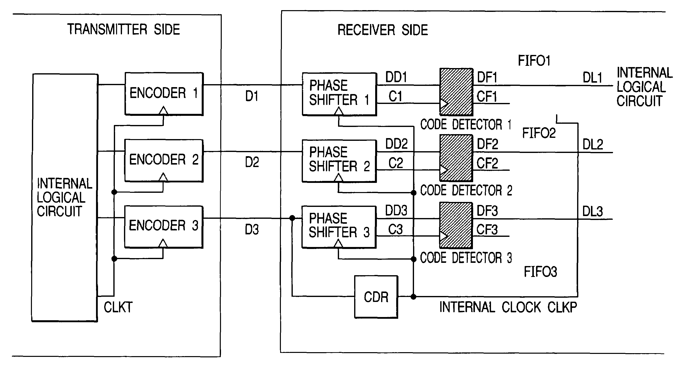
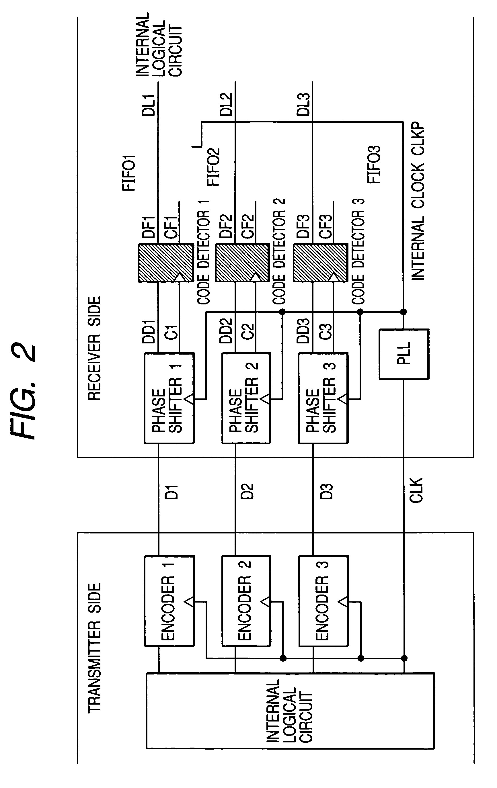
[0043]The preferred embodiment will be described in detail with reference to the accompanying drawings. In the following embodiment, the descriptions will be made with concrete numerical values for a quick understanding, however these numerical values are only for examples, and naturally these values will not restrict the invention at all. FIG. 2 illustrates a block diagram of the data communication system (communication with three channels for data and one channel for carrier clock) that incorporates a skew compensation system for parallel link. FIG. 3 illustrates a block diagram of the data communication system (communication with three channels for data) that incorporates a skew compensation system for parallel link.

[0044]FIG. 2 illustrates an example of a circuit configuration that compensates propagation time differences (skew) between input parallel data channels D1, D2, and D3 and an input clock channel (CLK), and synchronizes all the phases of the four channels D1, D2, D3, a...

embodiment 2

[0056]The preferred embodiment will be described in detail with reference to the accompanying drawings. In the following embodiment, the descriptions will be made with concrete numerical values for a quick understanding, however these numerical values are only for examples, and naturally these values will not restrict the invention at all.

[0057]FIG. 2 illustrates an example of a circuit configuration that compensates propagation time differences (skew) between input parallel data channels D1, D2, and D3 and an input clock channel (CLK), and synchronizes all the phases of the four channels D1, D2, D3, and CLK at the input stage of an internal synchronizing circuit. The transmitter side transmits D1, D2, D3, and CLK all in phase, however the characteristic dispersions on the propagation paths produce differences in the propagation time. As the result, the receiver side receives the clock and the data out of phase. Therefore, it is necessary to adjust the delay times between the clock ...

embodiment 3

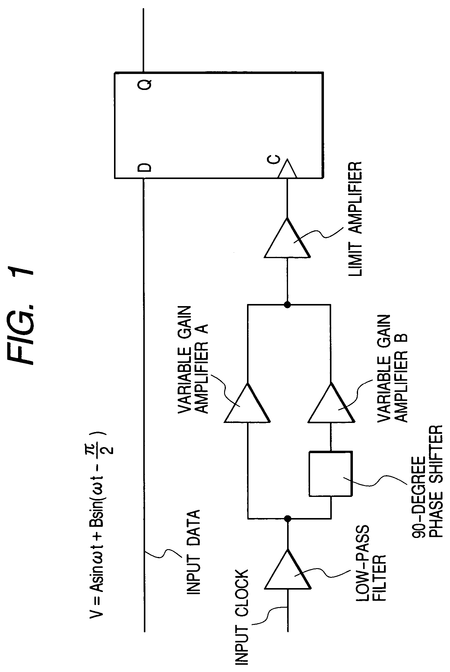
[0066]This embodiment is related with the skew compensation system for high-speed parallel signaling mentioned in the embodiment 1, which adopts a circuit configuration illustrated in FIG. 18 as an internal circuit of the phase shifter in replacement for the one illustrated in FIG. 1. The phase shifter illustrated in FIG. 18 incorporates a valuable phase adjustment system into the 90-degree phase shifter. A modification of the initial phase shift of 90° into that of 135°, for example, will realize the following operation that allows adjusting the time cycles of the phase adjustment, which cannot be achieved in the embodiment 1.

[0067]FIG. 9 illustrates the waveforms of the input signal to the limit amplifier. The amplitude of the input signal is expressed as follows.

V=A·sin(ωt)+B·sin(ωt−3π / 4)

Here, A, B represent the output amplitudes of the variable gain amplifiers A, B; ω the angular velocity of the based frequency; t the time; and V the amplitude of the signal. In FIG. 9, the notat...


PUM


Abstract

The invention intends to realize a high accuracy of some picoseconds in skew compensation as well as a downsized circuit scale. A phase shifter using analog circuits that allows a downsized circuit scale and a high-accuracy phase shifting is adopted in order to finely shift the phase between a clock signal and a data signal. The phase shifter passes the clock signal or the data signal through a low pass filter having a pass band not higher than the based frequency of the clock signal to extract the frequency factors not higher than the based frequency factors. After dividing the extracted signal into plural signals, the phase shifter inputs the clock signal or the data signal having the phase shifted to plural variable gain amplifiers. Next, the phase shifter inputs the outputs from the variable gain amplifiers to an adder or a subtracter, and inputs the signal after being added or subtracted to a limit amplifier to reshape it into a rectangular wave. Thus, by analogically adjusting the outputs from the variable gain amplifiers, the phase shifter shifts the phase of the input clock signal or data signal.

Description

FIELD OF THE INVENTION[0001]The present invention relates to an electronic circuit device that compensates (makes re-timing for) a propagation time difference (skew) between parallel synchronizing data and a clock signal inside a high-performance network apparatus and a computer system.BACKGROUND OF THE INVENTION[0002]A parallel optical link is effective in use for expanding the capacity of data connections inside and between the devices contained in a high-performance network apparatus and a computer system. The parallel optical link relates to the connections by a short distance data communication inside and between the devices, and to the communication technology that transmits signals, by driving in parallel optical signal transmission systems composed of optical signal-emitting elements, optical signal-receiving elements, and optical fibers. A use of the parallel optical link will achieve a large throughput data communication connection on a small device scale with a low delay....

Claims


Application Information

Patent Timeline
Patent Type & Authority Patents(United States)
IPC IPC(8): H04L7/00H04L27/08G06F1/10H03K5/08H03K5/13H03K5/131H03K5/135H04B10/07H04B10/2507H04B10/40H04B10/50H04B10/60H04L7/04H04L27/227
CPCH03K5/082H03K5/135H04L7/0037H04L27/2272H04L7/0008
Inventor NISHIMURA, SHINJIHARASAWA, KATSUYOSHI
Owner HITACHI LTD
Why Eureka
Try Eureka