
Method and plant for biological treatment of aqueous effluents for purification thereof

Inactive Publication Date: 2007-10-02
ONDEO DEGREMONT INC
View PDF12 Cites 14 Cited by
  • Summary
  • Abstract
  • Description
  • Claims
  • Application Information

AI Technical Summary

Benefits of technology

[0010]Thanks to these features according to the invention, the volume of the single aeration tank is reduced to the minimum by a factor of 10, in comparison with the activated sludge treatment tank of the conventional installations with prolonged aeration and low applied loading.
[0024]the very good quality of the very high loading sludge, which has a suspended matter concentration of the order of 0.5 to 2.5 g / l, preferably between 0.6 and 1.5 g / l (these values can be compared with the values of 3 to 4 g / l which are recommended in the prior art, particularly in FR-A-2 594 113) serves to apply high upward velocities (>2 m / h) in the clarifier which is associated with the single aeration tank, as described below;
[0027]The advantage of a system with a high or very high applied loading, according to the present invention, over the low loading systems, is considerable.
[0028]Such so-called “intensive” systems allow the design of much more compact structures with the same volume of incoming pollution to be treated, in terms of the aeration tank as well as the clarification system, the sludges having excellent settling properties.
[0033]The method according to the present invention is clearly distinguished from the prior art of the so-called very high loading methods, by specific conditions of use of the free culture, allowing for continuous growth in a lightly aerated medium and at high applied mass loading, to promote the mechanisms of biosorption and BOD storage.
[0038]The method covered by the invention, like any so-called intensive biological system, demonstrates very high responsiveness to the variations in the parameters of the untreated water.

Problems solved by technology

This explains why the installations of the prior art are costly, in terms of their construction as well as their operation and maintenance.

Method used


Image

  • Method and plant for biological treatment of aqueous effluents for purification thereof
  • Method and plant for biological treatment of aqueous effluents for purification thereof
  • Method and plant for biological treatment of aqueous effluents for purification thereof

Examples


Embodiment Construction

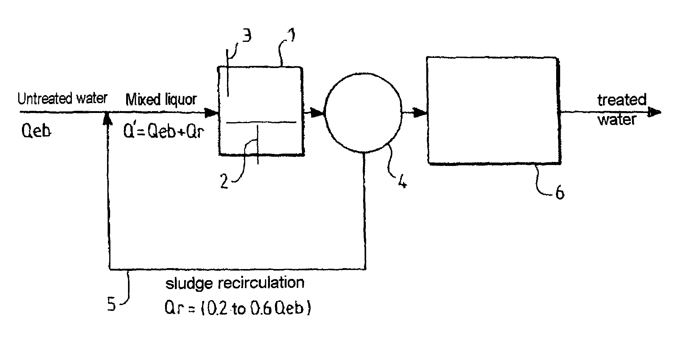
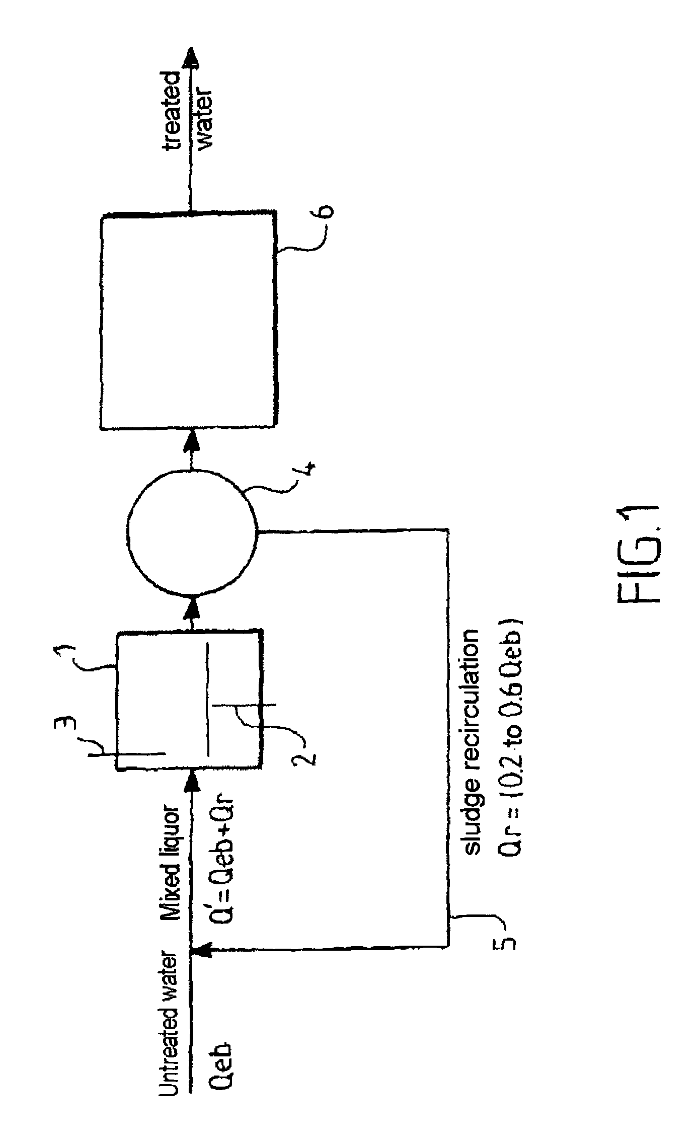
[0053]Reference to FIG. 1 shows that, in this embodiment, the device according to the invention comprises a reactor, or single aeration tank, with activated sludge under high loading, designated by the reference numeral 1, this reactor comprising continuous or intermittent air input means 2, the mixing energy being supplied mechanically, with a system for slaving to the dissolved oxygen content, and a turbidity measurement probe 3. In this embodiment, an intermediate settler 4 is associated with the reactor 1 in order to separate the sludge from the depolluted effluent. The installation further comprises a sludge recirculation circuit 5 from the intermediate settler 4 to the free culture reactor 1, the sludge recirculation rate (or sludge extraction rate from the intermediate settler 4) being slaved to the turbidity measurement supplied by the probe 3.

[0054]Together with this basic equipment of the device according to the invention, various means of a known type can be provided, ser...


PUM


Abstract

The invention relates to a method for the biological treatment of effluents contaminated with impurities of urban or industrial origin, characterised in employing a single aeration tank (1) with a high mass charge in which the raw effluent or mechanically pre-treated effluent is mixed without previous decantation with a free microbial culture of the activated sludge type, growing in a lightly aerated medium, of the order of 0.1 to 0.2 kg O2 / kg BOD5 removed, the organic charge applied having a value equal to or greater than at least 2 kg COD / kgSM / day, preferably equal to or greater than 4 kg COD / kgSM / day, the hydraulic residence time for the raw effluent in the single aeration tank being between 30 and 90 minutes, preferably between 40 and 60 minutes.

Description

FIELD OF THE INVENTION[0001]The present invention relates to the biological treatment of aqueous effluents, such as, in particular, domestic wastewater and industrial wastewater, for the purpose of their purification.[0002]More particularly, the invention relates to an improved method and device for the biological treatment of such effluents, employing free cultures of microorganisms according to the activated sludge technique in order to remove the carbon pollution present in the effluents to be treated.BACKGROUND OF THE INVENTION[0003]Among the known purification processes that use free cultures of microorganisms, those using so-called “low loading” activated sludges have come into increasingly frequent use.[0004]These methods of the “extensive” type have the feature of working with low applied mass and volumetric loadings, with high hydraulic residence times and a medium settling sludge, which leads to the construction of rather large structures, in terms of aeration tanks as wel...

Claims


Application Information

Patent Timeline
IPC IPC(8): C02F3/12C02F3/00
CPCC02F3/006C02F3/12Y10S210/908C02F2209/11C02F2209/22C02F2209/10Y02W10/10C02F3/00
Inventor MORGOUN, SERGE
Owner ONDEO DEGREMONT INC
Learn More