Adsorption systems using metal-organic frameworks

a technology of adsorption systems and metalorganic frameworks, applied in the direction of complex cyanides, lighting and heating apparatus, separation processes, etc., can solve the problems of complex control, large thermal mass, low cop (0, thermophysical property limitations of adsorbent-refrigerant combinations, etc., to achieve high mass loading, low heat of adsorption, and high heat dissipation efficiency

Inactive Publication Date: 2015-10-15
BATTELLE MEMORIAL INST +1
View PDF4 Cites 33 Cited by
  • Summary
  • Abstract
  • Description
  • Claims
  • Application Information

AI Technical Summary

Benefits of technology

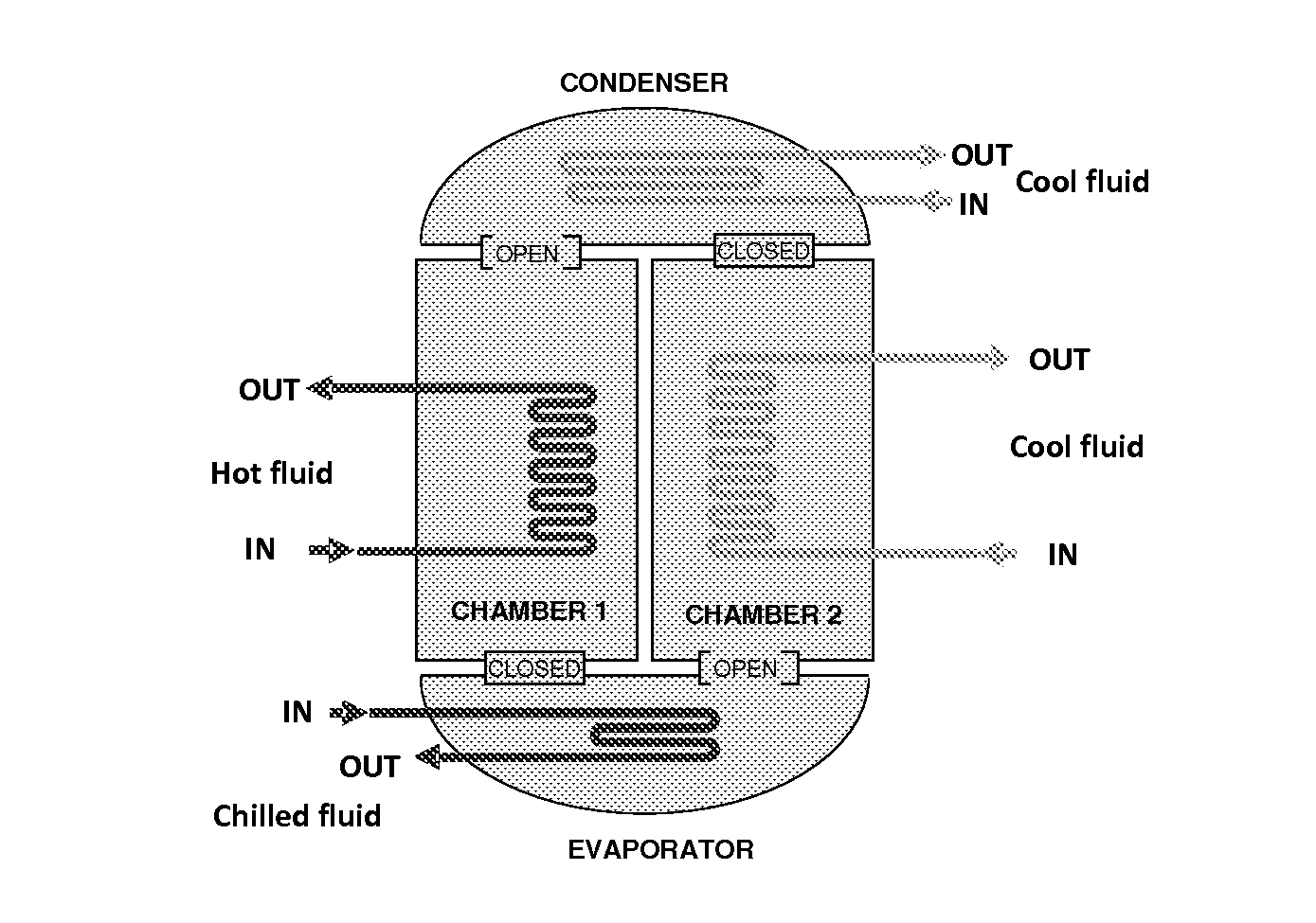
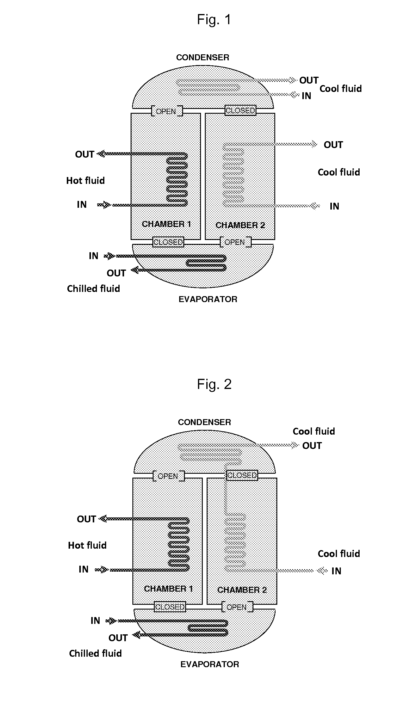
[0005]The present invention is directed toward adsorption systems having very high mass loading and relatively low heats of adsorption comprising certain combinations of refrigerants and sorbents such as metal-organic framework (MOF) which provide highly efficient adsorption chillers.

Problems solved by technology

Key disadvantages include large thermal mass, bulkiness, complex controls, and low COP (0.2 to 0.6).
These disadvantages arise mostly from thermophysical property limitations of adsorbent-refrigerant combinations presently available.
In the United States, various types of chiller technologies deployed in commercial buildings consume approximately 0.6 quads annually.
Key disadvantages of a typical adsorption chiller system include large thermal mass, bulkiness, and low COP (0.2 to 0.6).
The low COP is the most significant factor that drives up the size and cost of the units per ton of cooling capacity delivered and thus is a significant barrier to more widespread use of this technology.

Method used


Image

  • Adsorption systems using metal-organic frameworks
  • Adsorption systems using metal-organic frameworks
  • Adsorption systems using metal-organic frameworks

Examples


example 1

[0102]CuBTC and MDOBDC were synthesized and then water adsorption measurements were performed using an intelligent gravimetric gas analyzer (IGA).

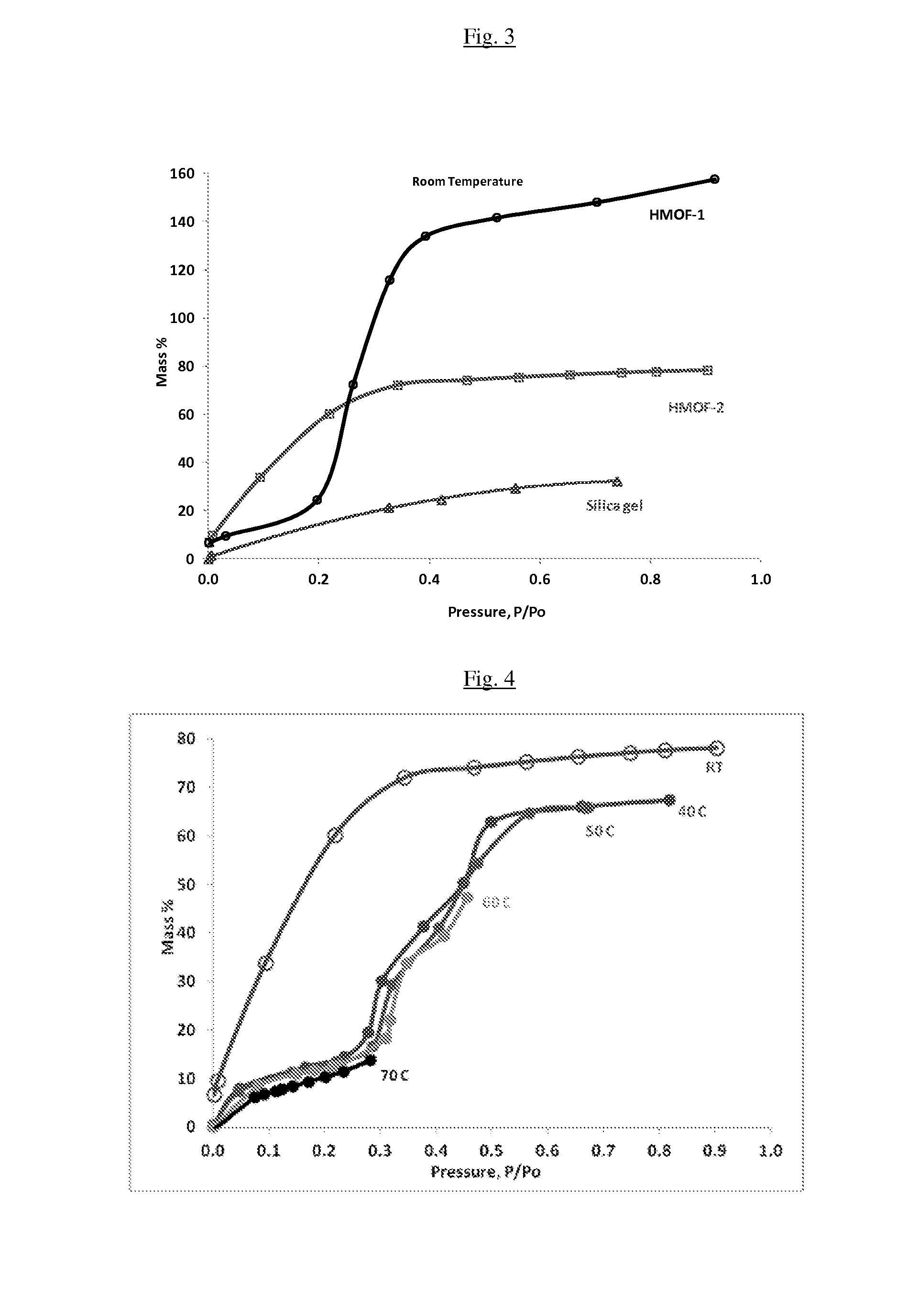
[0103]The mass uptake was measured as a function of pressure and the approach to equilibrium was monitored in real time. After equilibrium was established, the vapor pressure was increased to the next set pressure value, and the subsequent uptake was measured until equilibrium was reestablished. The increase in weight due to adsorption for each pressure step was plotted against the pressure. The adsorption of water in CuBTC was found to be 50 wt % at P / Po=0.3 or 10 mbar of pressure with very little desorption hysteresis. These results suggest that water loaded in CuBTC can be desorbed under a partial vacuum with very little additional heat input.

[0104]Using the method described above, water adsorption measurements were performed on MgDOBDC, NiDOBDC and CoDOBDC separately at room temperature. At P / P0=0.4, the water uptake in these three MOF...

example 2

[0105]Water adsorption experiments were performed on MIL-101(Cr), MIL-100(Fe), and CoCo. The sorption of water in MIL-100Fe was found to be 80 wt % at P / P0=0.9 with reversible adsorption and desorption of water molecules. The MIL-100Fe has pore diameters of 25 and 29 Å as confirmed by the single crystal X-ray diffraction. The MIL-101Cr was found to have mesoporous cage diameters of 29 and 34 Å. Water sorption of MIL-100(Fe) and MIL-101(Cr) indicate an uptake of 80 to 150 wt % at P / P0=0.9. The LZnPyCl showed a water update of 12 wt % at P / P0=0.95. Water sorption tests on CoCo indicate an uptake of water of 20 wt %. The results are summarized in FIGS. 7a, 7b, 7c and 7d.

example 3

[0106]Sorption experiments were conducted on MIL-101(Cr) (FMOF-1) with R-12 (dichlorodifluoromethane), R-125 (pentafluoroethane), R-143a (1,1,1-trifluoroethane), and R-22 (chlorodifluoromethane). Sorption experiments were conducted on MIL-100(Fe) (FMOF-2) with R-22 (chlorodifluoromethane). Results are summarized in FIG. 8.


PUM

PropertyMeasurementUnit
diameteraaaaaaaaaa
temperatureaaaaaaaaaa

Abstract

The present invention relates to sorbants such as metal-organic frameworks (MOFs), covalent organic frameworks (COFs), porous aromatic frameworks (PAFs) or porous polymer networks (PPNs) for separations of gases or liquids, gas storage, cooling, and heating applications, including, but not limited to, adsorption chillers.

Description

SUMMARY OF INVENTION[0001]The present invention relates to sorbants such as metal-organic frameworks (MOFs), covalent organic frameworks (COFs), porous aromatic frameworks (PAFs) or porous polymer networks (PPNs) for separations of gases or liquids, gas storage, cooling, and heating applications, such as, but not limited to, adsorption chillers.BACKGROUND OF INVENTION[0002]Adsorption cooling technology is an established alternative to mechanical vapor compression refrigeration systems. Adsorption-based refrigeration systems have several advantages including few moving parts, reduced vibration and lubrication requirements, and scalability to refrigeration load from a few watts to several kilowatts. Key disadvantages include large thermal mass, bulkiness, complex controls, and low COP (0.2 to 0.6). These disadvantages arise mostly from thermophysical property limitations of adsorbent-refrigerant combinations presently available.[0003]In the United States, various types of chiller tech...

Claims


Application Information

Patent Timeline
Patent Type & Authority Applications(United States)
IPC IPC(8): C09K5/04F25B15/00C01C3/11C07C65/03C07C63/28B01D53/02C07C63/307
CPCC09K5/047B01D53/02F25B15/006C07C63/307F25B2315/006C07C63/28C01C3/11B01D2253/204C07C65/03C07F11/005C07F15/025C07F15/045C07F15/065C07F19/005C07F1/005C07F3/003B01J20/226C09K5/14Y02A30/27F25B17/083
Inventor VAN HORN, BRETT L.BERTELO, CHRISTOPHER A.SILVERMAN, GARY S.MCGRAIL, B. PETERTHALLAPALLY, PRAVEEN K.MOTKURI, RADHA K.JENKS, JEROMY J.
Owner BATTELLE MEMORIAL INST
Why Eureka
Try Eureka