System and method for driving LED

Active Publication Date: 2007-10-02
CHEMTRON RES
View PDF5 Cites 326 Cited by
  • Summary
  • Abstract
  • Description
  • Claims
  • Application Information

AI Technical Summary

Benefits of technology

[0010]In still another embodiment of the invention, a sliding mode with pulse current averaging control for driving one or plurality of LEDs driver is proposed. The idea of pulsed current averaging is that in many switch-mode power supply topologies, it is possible to measure input or inductor current in order to obtain an accurate estimate of output current. Sometimes this is called an “estimator” or “observer” by control theorists. Thus, in applications such as those that require output current regulation, this becomes a powerful tool to help controller design. Remarkably, digital implementation of the approach should not require additional analog-digital (A/D) or D/A converters because of some of its special features. Thus, it is possible to get advanced digital performance at substantially reduced monetary cost. Traditionally, in peak current mode control regulation, a user specifies a reference current, and then the power switch switches off when the inductor current rises to this reference current (minus an appropriate slope compensation to maintain global stability). However, in pulsed current averaging, we propose to regulate

Problems solved by technology

An LED, having a diode type volt amp characteristic, presents a very difficult load for a voltage type regulators.
In practically all switching LED drivers current through LED is a

Method used


Image

  • System and method for driving LED
  • System and method for driving LED
  • System and method for driving LED

Examples


Example

[0037]The embodiments of the present invention will be described below with reference to the accompanying drawings. Like reference numerals are used for like elements in the accompanying drawings.

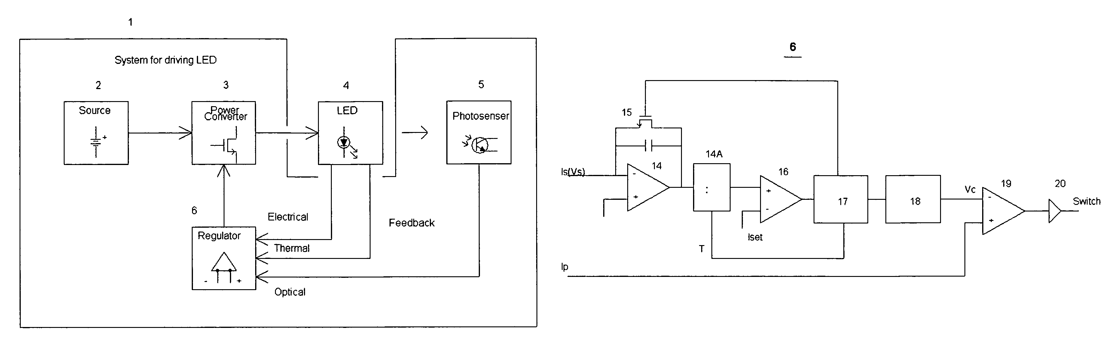
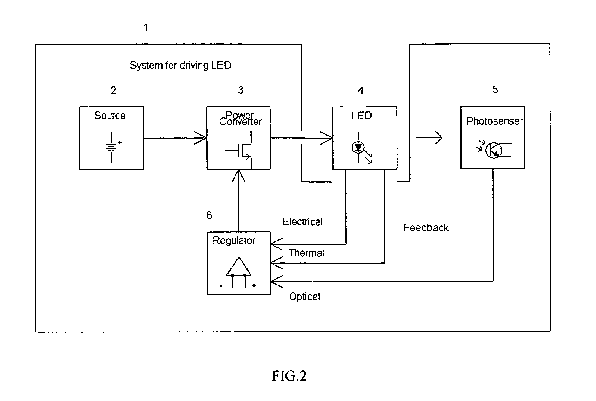
[0038]FIG. 2 is a system for driving one or plurality of LEDs, according to one embodiment of the invention. The system 1 includes an energy source 2 and a switching power converter 3 driving a string of LEDs 4. The performance of LEDs is measured by electrical and thermal sensors (not shown separately from LED unit 4) and a photosensor 5. These sensors generate electrical, thermal and optical feedback channels coupled with a regulator 6 controlling the output of the power converter 3. The regulator 6, according to one embodiment of the invention, needs to have as minimum a single electrical feedback. Yet, it may use additional thermal and optical feedback channels for enhanced performance, according to another embodiment of the invention. The energy source 2 is an AC / DC converter, connecte...


PUM


Abstract

A system drives one or plurality of LEDs regulating their brightness by controlling LEDs average current or voltage. The system includes a switching power converter and an integrated digital regulator with at least one of electrical, thermal and optical feedbacks. The regulator is constructed as a hysteretic peak current mode controller for continuous mode of operation of the power converter. For discontinuous mode of operation of the power converter a pulse averaging sliding mode control is being used. Average LED current is measured by integrating LED pulse current at off time and hysteretically adjusting on time of the power switch. Input battery is protected from discharging at abnormally low impedance of the output.

Description

RELATED APPLICATIONS[0001]This application claims priority from co-pending U.S. provisional patent application Ser. No. 60 / 611,539 entitled SYSTEM AND METHOD FOR DRIVING LED, filed on Sep. 21, 2004.FIELD OF THE INVENTION[0002]The present invention relates generally to power conversion, and more specially, to a system and method for driving LEDs, and particularly to integrated LED drivers with digital controllers.BACKGROUND OF THE INVENTION[0003]It is known in the Industry a few LEDs drivers, like charge pump with the multi output current mirror from National Semiconductor. These drivers cannot economically boost input voltage more than 1.5 to 2 times and therefore do require parallel circuits for identical drive of multiple LEDs. That makes these drivers large and expensive. Also, required in this case, a linear current regulator in each channel compromises the efficiency of an LED driver.[0004]It is also known an inductor based boost converter, like LT 1932 from Linear Technology™ ...

Claims


Application Information

Patent Timeline
IPC IPC(8): G05F1/00G05F1/40H02M1/00H05B44/00
CPCH02M3/157H05B33/0815H05B33/086H05B33/0818H05B33/0872G05F1/618H05B37/02H05B33/0869H02M2001/0009Y02B20/341H05B45/20H05B45/22Y02B20/30Y02B20/40H05B45/3725H05B45/12H05B45/38H05B45/10H05B45/56H05B47/105H05B47/165H02M1/0009H05B47/11
Inventor SHTEYNBERG, ANATOLYRODRIGUEZ, HARRY
Owner CHEMTRON RES
Why Eureka
Try Eureka