Image processing apparatus, image processing method, and storage medium of image processing program

a technology of image processing and image data, applied in image watermarking, instruments, secret communication, etc., can solve the problems of deteriorating image quality, difficult to detect information from image data under stable conditions, and no digital watermarking technique used via non-electronic media

Inactive Publication Date: 2007-10-02
FUJIFILM BUSINESS INNOVATION CORP
View PDF11 Cites 18 Cited by
  • Summary
  • Abstract
  • Description
  • Claims
  • Application Information

AI Technical Summary

Benefits of technology

[0025]As previously explained, since the present invention is applied, both the image processing apparatus and the image processing method can be provided, and further, the digital watermarking technique having the print-resisting characteristic can be provided, while the degradation of the image qualities are suppressed to the minimum allowable values. When the additional signal is detected, most of parameters required while the additional signal is embedded are no longer grasped as initial knowledge, and also, such parameter information need not be received by employing other transfer unit. As a consequence, the present invention can provide both the image processing apparatus and the image processing method, which can be utilized in any combinations of large numbers of image input / output devices.

Problems solved by technology

However, the major digital watermarking techniques have been employed via electronic media, whereas substantially no digital watermarking technique has been used via non-electronic media such as paper.
That is, when image data stored in a computer is printed out and thereafter the printed image is scanned to be inputted into the computer, since the image data accepts various image converting operations, there is such a problem that it is practically difficult to detect information from the image data under stable condition while a deterioration of image qualities is suppressed.
Also, in the case that a digital camera is employed as an image input device, there is another problem of aberration.
However, since precision as to printers, scanners, digital cameras and the like is increased, necessities of digital watermarking techniques are increased which can be applied to printing fields, although these problems are still left.
However, in this conventional technique, since the rectangular area formed by the plural pixels is employed in order to represent a 1-bit signal, if an amount of information which is embedded into an entire image is increased, then there are such problems that the size of the rectangular area is decreased and the gradation characteristic is decreased.
In addition, the following practical difficulty may be readily supposed.
That is, since no specific measure has been taken in order to detect the rectangular area from a printed image, it is practically difficult to actually detect the rectangular area so as to identify the additional information.
This conventional technique owns such a problem that since the additional information is added in the halftone process operation, this technical idea cannot be applied to another printer capable of executing another halftone process operation different from the above-explained halftone process operation.
As a result, for instance, as to an image which has been enlarged, or reduced after being printed, there is such a problem that additional information cannot be acquired from this printed image.
It is difficult to find out such a block corresponding to the original block into which the registration signal has been embedded from the image whose resolution has been converted.
Also, even if such a block could be detected, the following problem occurs.
Also, in such a case that the block size used when the additional information is embedded is changed, the following problem may also occur.
That is, if this change of the block sizes is not precisely notified, then the additional signal cannot be decoded.
However, in such a case that if the block size is not known on the detection side, then the additional signal cannot be decoded, the management as to the devices provided on the detection side becomes complex.
However, no measure is taken to such a fact that the resulting image quality is degraded.
As a consequence, there is only such a measure that such additional information with a small amplitude is embedded, by which the degradation of the image quality do not become conspicuous, so that this additional information can be hardly detected.
However, the recovery steps become complex, and the embedding information amount is decreased.
Furthermore, since both the registration signal used to detect the enlarging ratio and the information to be transferred are embedded by using the different embedding methods, another problem may occur.
That is, the registration signal may interfere with the information to be transferred.

Method used


Image

  • Image processing apparatus, image processing method, and storage medium of image processing program
  • Image processing apparatus, image processing method, and storage medium of image processing program
  • Image processing apparatus, image processing method, and storage medium of image processing program

Examples


first embodiment

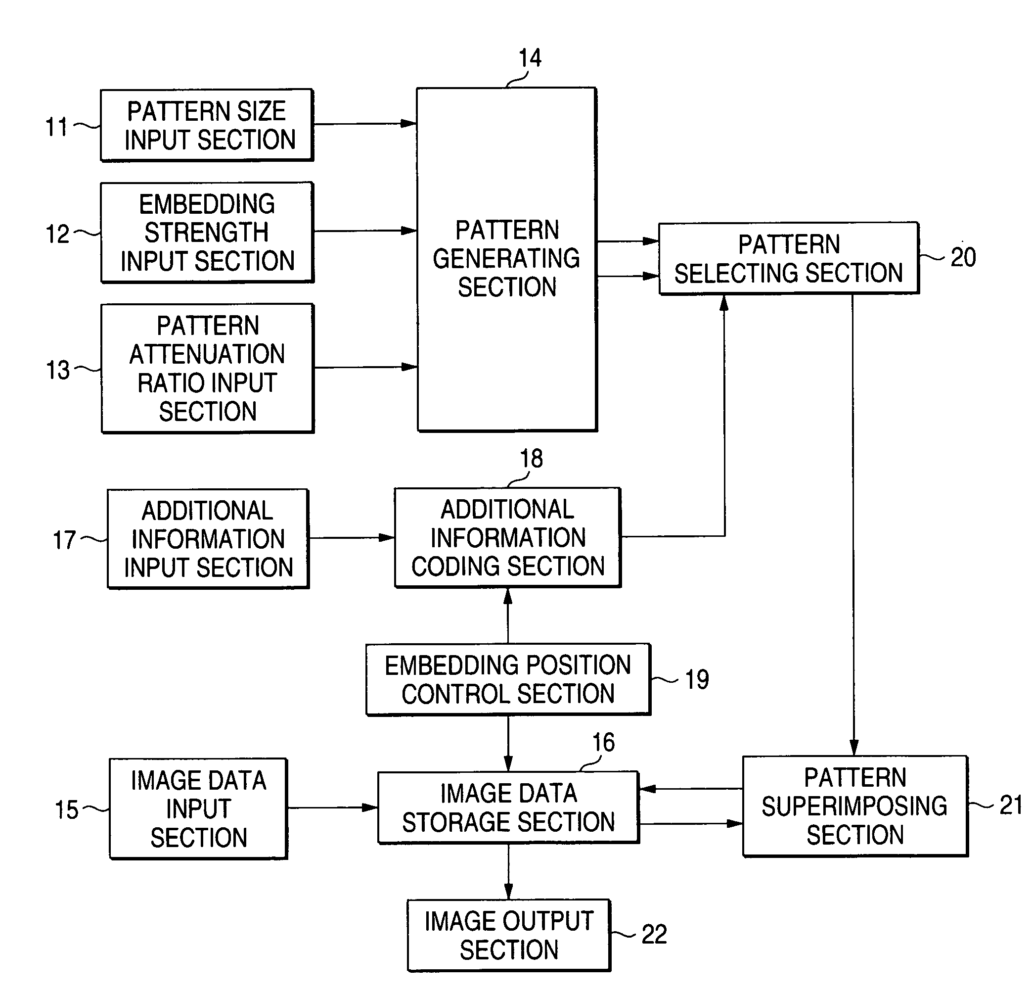
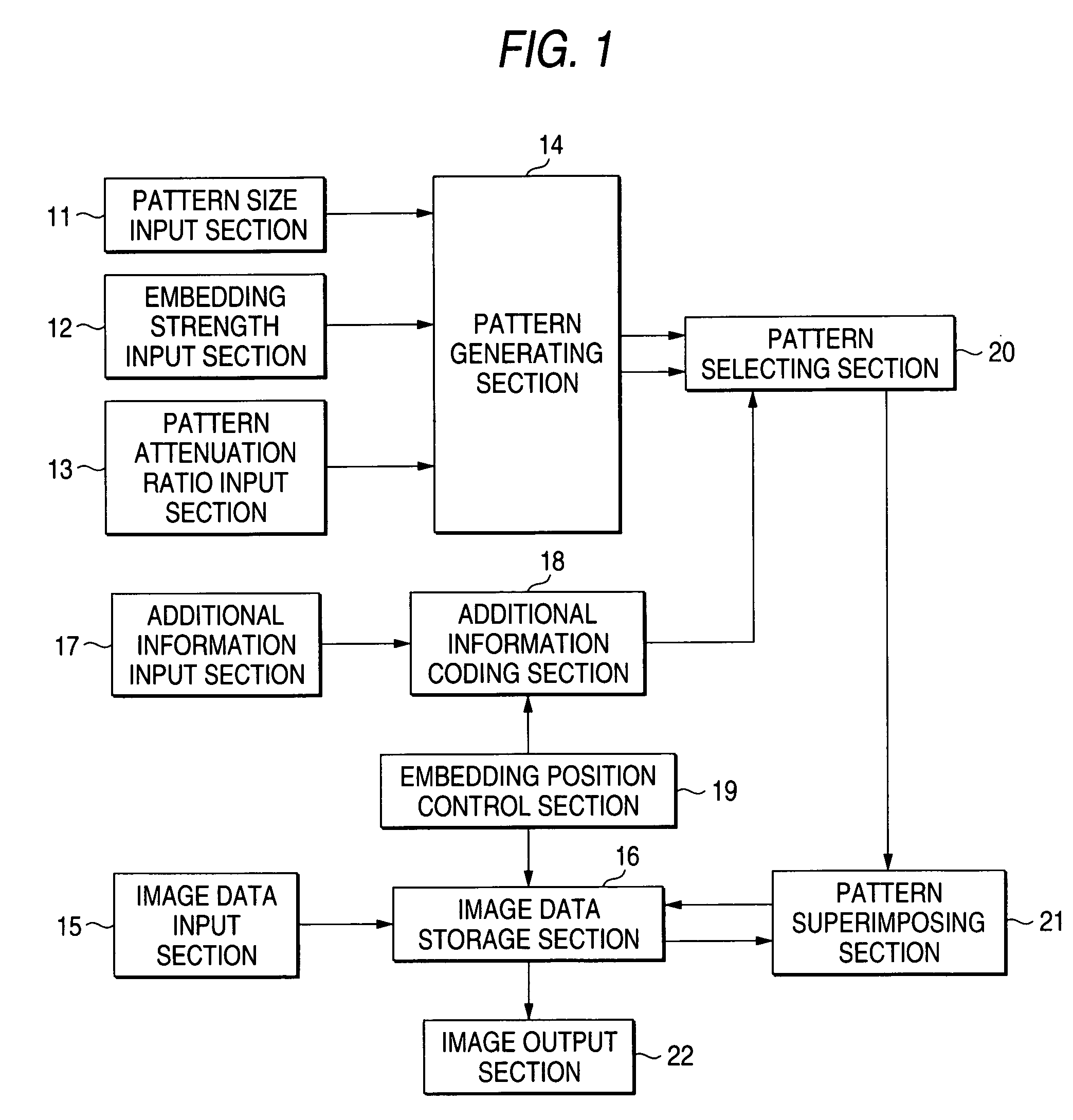
[0047]FIG. 1 is a block diagram for indicating one structural example of an additional information embedding side according to a first embodiment of the present invention. In this drawing, reference numeral 11 denotes a pattern size input section; reference numeral 12 indicates an embedding strength input section; reference numeral 13 represents a pattern attenuation ratio input section; reference numeral 14 denotes a pattern generating section; reference numeral 15 denotes an image data input section; reference numeral 16 indicates an image data storage section; reference numeral 17 represents an additional information input section; reference numeral 18 denotes an additional information coding section; reference numeral 19 is an embedding position control section; reference numeral 20 represents a pattern selecting section; reference numeral 21 denotes a pattern superimposing section; and reference numeral 22 indicates an image output section.

[0048]The pattern size input section 1...

second embodiment

[0125]Next, a description will now be given on a second embodiment of the present invention. FIG. 17 is a block diagram for indicating one structural example of an additional information embedding side according to the second embodiment. It should be noted that the same reference numerals shown in FIG. 1 will be employed as those for denoting the same, or similar structural elements ofFIG. 17, and explanations thereof may be omitted. Reference numeral 61 indicates a pattern attenuation ratio calculating section. In this second embodiment, while this pattern attenuation ratio calculating section 61 is provided instead of the pattern attenuation ratio input section 13, a pattern attenuation ratio is acquired by way of a calculation.

[0126]The pattern size input section 11 selects an image output device to which a user has previously been registered via either a personal computer or an operation panel, which are not shown. Since this output device is selected, the pattern size input sec...

third embodiment

[0136]Next, a description will now be given on a third embodiment of the present invention. FIG. 19 is a block diagram for indicating one structural example of an additional information embedding side according to the third embodiment. It should be noted that the same reference numerals shown in FIG. 1 will be employed as those for denoting the same, or similar structural elements of FIG. 19, and explanations thereof may be omitted. Reference numeral 71 indicates an embedding strength control section; reference numeral 72 shows a minimum embedding strength input section, and reference numeral 73 represents a maximum embedding strength input section. In the above-described respective embodiments, the pattern is embedded at a constant embedding strength irrespective of the inputted image data. As a result, the patterns are embedded at the same strengths even in the flat portion where the embedded pattern can be easily identified, and also even in such a place where the strong edge is ...


PUM


Abstract

A pattern generating section forms two patterns based on a pattern size, an embedding strength, and a pattern attenuation ratio. When corresponding pixels in two patterns are added to each other, all of elements become zero. When all of pixels in each of patterns are added to each other, the added pixels become zero. Each of patterns has two edges, which include discontinuous pixel values and pass through a center portion of each of patterns in difference directions from each other. Absolute values of pixel values of the patterns are the largest at a center thereof. The absolute values of pixel values of the patterns decrease as being away from the center thereof. A pattern selecting section selects one of the two patterns in response to additional information. A pattern superimposing section superimposes the additional information on the image data to embed it into the image data.

Description

[0001]The present disclosure relates to the subject matter contained in Japanese Patent Application No. 2002-244312 filed on Aug. 23, 2002 and Japanese Patent Application No. 2002-312315 filed on Oct. 28, 2002, which are incorporated herein by reference in its entirety.BACKGROUND OF THE INVENTION[0002]1. Field of the Invention[0003]The present invention is related to a method and an apparatus for embedding information into an image represented by multi-gradation, and related to a method and an apparatus for detecting information embedded in an image, and also related to a storage medium of an image processing program.[0004]2. Description of the Related Art[0005]Very recently, digital watermarking techniques by which electronic information is added in such a format that this electronic information cannot be visibly recognized by human eyes at a glance have been actively researched / developed. Then, these digital watermarking techniques have been utilized by way of various modes. Howev...

Claims


Application Information

Patent Timeline
Patent Type & Authority Patents(United States)
IPC IPC(8): H04K1/00G06T1/00H04N1/387
CPCG06T1/005H04N1/32208H04N1/32309G06T2201/0051G06T2201/0065G06T2201/0061
Inventor IHARA, FUJIO
Owner FUJIFILM BUSINESS INNOVATION CORP
Why Eureka
Try Eureka